
Valeo compressors performance tool - performance tool
The C-type insert, on the other hand, has a much better positioning from this point of view, since two of its sides are all positioned in the insert slot. This aspect becomes important when we have to start using the inserts in roughing operations when depth of cut and feed rates are high. The fact of having better stability in the case of the C insert is a fundamental advantage for cutting edge life and machining success.
PVD (Physical Vapor Deposition) and CVD (Chemical Vapor Deposition) coatings possess advanced coating architectures which provide a multiplicity of surface characteristics not attainable with standard coating treatments. Special sputtering techniques, low-pressure plasma treatments and specialized equipment enable full coverage of complex, intricate tooling geometries and create a variety of unique material properties.
TurninginsertIdentification chart
Look at how the inserts are mounted on their respective tools; we should notice that the W-shaped insert would offer a slot with a more open contact angle due to its shape.
ISOinsertchart
The first letter of the code is perhaps the most important one, that is the one that every turner must surely know because it defines the shape of the insert. In this lesson we have seen them all, although as we have said, in reality the most common shapes are as follows:
Let’s take a closer look at some practical aspects of the C and W shape inserts. Let’s compare them on the assumption that they have the same nose radius, the same solid carbide grade and identical chipbreaker geometry.
ANSIinsertnomenclature
First of all, I would like to remind you that you can download the scheme of the ISO insert nomenclature. Keep it handy during today’s lesson and the next one, by clicking on the icon at the bottom right of the video. It will also come in handy on the machine. ISO insert nomenclature In today’s lesson we looked at the first part of the ISO insert nomenclature for mechanically fixed inserts. To be precise we looked at the first 4 letters. The first letter of the code is perhaps the most important one, that is the one that every turner must surely know because it defines the shape of the insert. In this lesson we have seen them all, although as we have said, in reality the most common shapes are as follows: As we said in the lesson, the choice of shape influences the strength of the insert and its versatility in making profiles. Among the various shapes, we find exactly in the centre the C and W shapes. Both have an angle between the cutting edges of 80° and both, for one reason or another, are among the most popular. C and W in comparison Let’s take a closer look at some practical aspects of the C and W shape inserts. Let’s compare them on the assumption that they have the same nose radius, the same solid carbide grade and identical chipbreaker geometry. C and W have different shapes – the first trigonal and the second rhomboidal – but both, once placed on the respective tool, tackle the machining with the same 95° tool cutting edge angle and therefore with a 5° lead angle. From the point of view of versatility, so the number of possible operations, both tools would be similar. Therefore they would be able to carry out the exact same machining operations for us operators: turning of various types, shouldering, chamfers and radius. So which one are we going to use? First of all, let’s start by counting the number of cutting edges useful for our machining; the trigonal insert with its 6 cutting edges would be the master. The more cutting edges, the more pieces produced. Moreover, since the purchase cost of both inserts would be the same, the cost per cutting edge would be considerably in favour of the W-type insert; therefore, it will be cheaper per cutting edge. The W-type insert would definitely be the winner so far. But does this way of thinking fit well with our chip volume and productivity? Is this really the most economical way? Of course, we would say yes if we stopped at this level. But we like to go into each topic in depth, so let’s think about it. Look at how the inserts are mounted on their respective tools; we should notice that the W-shaped insert would offer a slot with a more open contact angle due to its shape. The C-type insert, on the other hand, has a much better positioning from this point of view, since two of its sides are all positioned in the insert slot. This aspect becomes important when we have to start using the inserts in roughing operations when depth of cut and feed rates are high. The fact of having better stability in the case of the C insert is a fundamental advantage for cutting edge life and machining success. It is probable that the W-type insert will fail when heavily loaded due to the micro-vibrations created by the precarious fixing. Consequently, it is no longer so certain that we can use all 3 of its cutting edges, contrary to what happens with the C-shaped insert where we can certainly use both cutting edges. In our opinion, it should be used, for example, on machines where the working data are not so demanding. Its operations could be finishing and semi-finishing on materials that are not particularly difficult to machine. Because of its versatility and not only because of the number of operations it can perform but also because of the number of possible applications, from roughing to finishing, the C-type insert is undoubtedly the most widely sold and used insert in machine shops all over the world. It could be said that the C shape combined with its 95° lead angle has made the fortune not only of the insert manufacturers but also of us operators and workshop technicians, who have solved many problems with the use of this tool. In addition, the C shape placed on a different tool with a different lead angle would have a way of working with the so-called 100° recovery angle. In this way, the C-type insert would have 4 cutting edges instead of 2, making it one of the most affordable inserts. Used with recovery angles, it would certainly not be able to perform countless movements on the workpiece or remove large amounts of material. But within its field of application it would remain useful, also because the recovery angle assumes that the insert works at an angle between the cutting edges of 100°, so it is also very strong. This solution is successfully used in various sectors, for example when machining the surfaces of forged parts, roughing eccentric components where the interrupted cut affects the life of the insert. The first cut is often made in this way in order to improve and optimise production costs.
Please complete our Coating Requirement Questionnaire or call us at 1.800.336.3872 to review & discuss your project requirements. Submit Requirements Online
It is probable that the W-type insert will fail when heavily loaded due to the micro-vibrations created by the precarious fixing. Consequently, it is no longer so certain that we can use all 3 of its cutting edges, contrary to what happens with the C-shaped insert where we can certainly use both cutting edges.
ISOinsertnomenclature pdf
As we said in the lesson, the choice of shape influences the strength of the insert and its versatility in making profiles.
Among the various shapes, we find exactly in the centre the C and W shapes. Both have an angle between the cutting edges of 80° and both, for one reason or another, are among the most popular.
ISO turninginsertnomenclature

In our opinion, it should be used, for example, on machines where the working data are not so demanding. Its operations could be finishing and semi-finishing on materials that are not particularly difficult to machine.
Step 3: Different materials can be deposited in different forms (polycrystalline, amorphous, monocrystalline etc.) to meet certain functional objectives. Such materials include, but are limited too:
Carbide insertidentification chart PDF
Step 3: Metal vapors aredeposited on your substrate via an evaporation and ionization process. Single or multi-layer coatings may be applied in one processing cycle. Such materials may include, but are not limited to:
C and W have different shapes – the first trigonal and the second rhomboidal – but both, once placed on the respective tool, tackle the machining with the same 95° tool cutting edge angle and therefore with a 5° lead angle. From the point of view of versatility, so the number of possible operations, both tools would be similar. Therefore they would be able to carry out the exact same machining operations for us operators: turning of various types, shouldering, chamfers and radius.
Insertdesignation chart
Because of its versatility and not only because of the number of operations it can perform but also because of the number of possible applications, from roughing to finishing, the C-type insert is undoubtedly the most widely sold and used insert in machine shops all over the world. It could be said that the C shape combined with its 95° lead angle has made the fortune not only of the insert manufacturers but also of us operators and workshop technicians, who have solved many problems with the use of this tool. In addition, the C shape placed on a different tool with a different lead angle would have a way of working with the so-called 100° recovery angle. In this way, the C-type insert would have 4 cutting edges instead of 2, making it one of the most affordable inserts.
In today’s lesson we looked at the first part of the ISO insert nomenclature for mechanically fixed inserts. To be precise we looked at the first 4 letters.
First of all, let’s start by counting the number of cutting edges useful for our machining; the trigonal insert with its 6 cutting edges would be the master. The more cutting edges, the more pieces produced. Moreover, since the purchase cost of both inserts would be the same, the cost per cutting edge would be considerably in favour of the W-type insert; therefore, it will be cheaper per cutting edge. The W-type insert would definitely be the winner so far.
Used with recovery angles, it would certainly not be able to perform countless movements on the workpiece or remove large amounts of material. But within its field of application it would remain useful, also because the recovery angle assumes that the insert works at an angle between the cutting edges of 100°, so it is also very strong. This solution is successfully used in various sectors, for example when machining the surfaces of forged parts, roughing eccentric components where the interrupted cut affects the life of the insert. The first cut is often made in this way in order to improve and optimise production costs.
ISOcarbide Insertchart
But does this way of thinking fit well with our chip volume and productivity? Is this really the most economical way? Of course, we would say yes if we stopped at this level. But we like to go into each topic in depth, so let’s think about it.
Step 4: Our proprietary PVD coating systems possess precision thin film architectures. The average thickness of our various PVD coatings range from 2-5 microns (0.00008" - 0.0002") per surface.
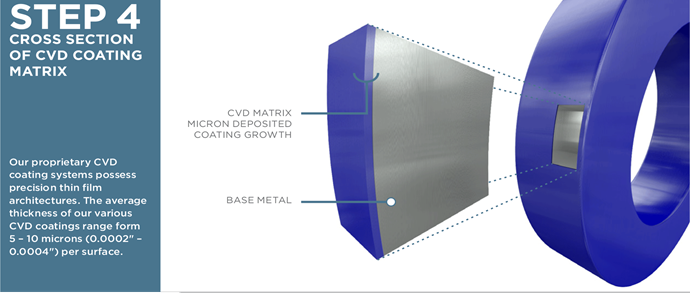
Step 4: Our proprietary CVD coating systems possess precision thin film architectures. The average thickness of our various CVD coatings range from 4-12 microns (0.0002" - 0.0005") per surface.
Specific coatings are FDA compliant, USDA approved and biocompatible with ISO 10993 and commonly used in industries such as food packaging and food processing.
Primary surface enhancements of pvd coatings and cvd coatings include extraordinary resistance to wear and hardness, and may also include non-wetting, dry lubrication, low friction, corrosion protection, heat transfer, or resistance to thermal oxidation.
First of all, I would like to remind you that you can download the scheme of the ISO insert nomenclature. Keep it handy during today’s lesson and the next one, by clicking on the icon at the bottom right of the video. It will also come in handy on the machine.
At Endura Coatings, we offer the Series 600 PVD / CVD coatings. As part of our pricess we have 4 steps for these coatings.


 0086-813-8127573