
What does SFM mean? - what does sfm mean
The Dimension tool for drawings work much like the Dimension tool for sketches. Activate the tool (click the icon or use the d shortcut), then:
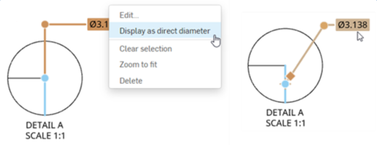
To convert the foreshortened diameter dimension format to a direct dimension, right-click on the diameter and select Display as direct diameter (below left). This replaces the foreshortened dimension with a direct dimension (below right). This option is a toggle, so you can switch between the dimension styles at any time.
This carbide straight router bit features a cutting diameter of 1/4" and a cutting length of 1-1/2" with an overall length of 3-5/16". The shank is 1/4" in diameter.
You can edit grip points of an existing dimension, if necessary. Click and drag any grip point to another edge, point, arc, circle, or circle center. Associations are maintained on other grip points. For example, in the illustrations below, the right grip point of the dimension is dragged from the point to the edge:
Placing a diameter dimension on a detail view or crop view of an arc or circle displays a foreshortened diameter dimension, as shown below.
Midpoints and quad points are disabled during dimensioning for ease of selecting appropriate dimension points. However, after a dimension has been placed, editing the dimension provides access to these midpoints and quad points. Use keyboard shortcut Shift+q to quickly toggle on midpoints and quad points for the current command. Shift+q again to toggle them off.
You can use the Line-to-line tool to automatically add a diameter symbol in the same way as with the Dimension tool. The line-to-line tool works on both projected and section views.
You can automatically dimension the wall thickness of two concentric circles or arcs. After selecting the Dimension tool, click each circle or arc and drag to place the dimension. The tool automatically dimensions the linear distance between the two circles or arcs:
Drag that grip point across one of the infinite lines through the ends of the selected edges/points to change the measured value.
You can edit a dimension after placement by clicking and dragging a grip point. As you move the cursor, drawing entities highlight to indicate you can dimension to them.
Instructions: Slowly dial up the RPMs on your router to the recommended maximum. Then, dial back if needed to find the “sweet spot”. The sweet spot is the speed at which the least resonant vibration is present. If the sweet spot cannot be achieved within 5,000 RPMs of the max, check the collet for residue or other debris and start over.
It is possible to automatically add a diameter symbol to a linear dimension if the lines selected are on the same edge representing an arc or circle on its edge. See Linear dimensions on circular parts.
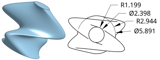
To create a foreshortened diameter dimension for a non-cylindrical feature, select a centerline and the corner, point, or axis of choice. Selecting the foreshortened dimension highlights the reference point or edge and centerline.
Below are entity-specific dimension tools. For each tool, only specific entity types are highlighted as you move the cursor.
Use the right-mouse click to open a context menu on any dimension to access a list of command options for that dimension. These command options are listed below. Not all the commands listed here are available for every type of dimension.
Dimensions can be created not only for the angle, but also for its conjugate/reflex and supplementary angles. The example below displays two sketch lines in blue. The angle of 116.4°, its conjugate/reflex angle of 243.6°, and the supplementary angles of 63.6°, are all dimensioned.
Place a minimum or maximum dimension directly to any combination of arcs, circles and any other geometry type, excluding curves.
When you choose units, you set two properties in the drawing or on a dimension - the Units property and the Fractional display property.
You can also add a Diameter dimension to circles that are on either side of other geometry. For instance, the top and bottom circles below have two ellipses between them. The four sketches are lofted, and then a top view is placed in a Drawing. Diameter dimensions are then added to both circles. If the circle is obscured, as is the case in the bottom circle in this example, a guide line is overlaid on top, as you add the dimension, ensuring the visibility of the circle.
When an edge is selected, click again (even while dimensioning) to deselect it and select a different edge.
Right-click on the dimension and select Break dimension or Unbreak dimension from the context menu. Only one of the intersecting lines may be broken.
You can customize the appearance of a selected dimension with the Dimension palette. Selecting a dimension causes the dimension palette icon to appear.
If you use an ANSI or ISO template when creating a new drawing, the ordinate dimension style defaults to ANSI or ISO, respectively.
Dimensions in toolinggranger
When you select dimensions, a node displays near dimension arrows or ticks. Clicking a node flips the arrows of the dimension.
You can change the way intersecting dimension lines are displayed: as broken where they intersect or as unbroken where they intersect.
Drag the grip point across one of the infinite lines through the ends of the selected edges/points to change the measured value to the supplementary or vertical angle of the angle where the text was first placed.
Create ordinate dimensions (X, Y pairs) for a feature measured from a datum. Ordinate dimensions created as a group move together when one is moved.
By default, the jog will appear at the midpoint of the extension line. Hover over dimension lines to highlight the snap points, then click and drag the snap points on the jogged extension line to position them to your preference:
When defining dimensions for a drawing, you will notice that orange snap points appear when you hover over a line or point. There are 5 types of snap points:
Choosing any of: Inches, Inches fractional, Millimeters, or Feet and Inches overrides the units for that dimension. If you later change the drawing units, the units for the dimension are not overridden. But you can change the units back to (Drawing) if you want to inherit the drawing properties again.
Warning: Make sure the router bit is properly fastened and tightened in the router’s collet and the bit can rotate freely without any obstructions.
You can also add a Radial dimension to circles that are on either side of other geometry. For instance, the top and bottom circles below have two ellipses between them. The four sketches are lofted, and then a top view is placed in a Drawing. Radial dimensions are then added to both circles. If the circle is obscured, as is the case in the bottom circle in this example, a guide line is overlaid on top, as you add the dimension, ensuring the visibility of the circle.
If the orientation of the ordinate dimension is not correct, move the mouse around the datum point until the 0,0, dimension is in the correct orientation, then click to set its location on the drawing.
It is possible to automatically add a diameter symbol to a linear dimension if the lines selected are on the same edge representing an arc or circle on its edge. This works in projected views only.
Hover over a marker to wake up alignment. This is available in Preview mode only. Pass over other drawing entities to wake up alignment as well, like other views’ entities.
The bold datum point (.963 to the left, above) is the point being realigned; the red crosses (plus signs) on each datum point are alignment snap indicators
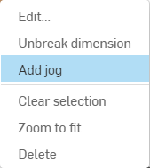
To clarify dimensions that are very close to each other, you can use jogged dimension extension lines. To add a jog to an extension line, right-click on the extension line to open the context menu, then click Add jog:
Once the snap point is visible, the point has been snapped to and you can click. There is no need to click directly on the point once it is visible. While moving the mouse to place the dimension, you'll notice thin, dashed lines as the cursor passes near other entities. These are inferencing lines that you can align the dimension to; simply click when you see the line appear to align the dimension to that line.
The image below shows a projected side view of a cylinder part. Select the top corner snap point. Then select the bottom corner snap point. This results in a normal linear dimension, as shown below left. However, if you first select the top edge, and then select the bottom edge, this results in the same linear dimension, but with the diameter symbol applied (shown below right).
Measure the interior angle between the two legs and the exterior angle formed by two lines. Click . Click two lines.Move the cursor between the lines to preview the inner angle dimension.Line-to-line angular dimensions have a drag-able grip on the dimension arc for changing the angle to be measured:Drag the grip point across one of the infinite lines through the ends of the selected edges/points to change the measured value to the supplementary or vertical angle of the angle where the text was first placed.Dimensions can be created not only for the angle, but also for its conjugate/reflex and supplementary angles. The example below displays two sketch lines in blue. The angle of 116.4°, its conjugate/reflex angle of 243.6°, and the supplementary angles of 63.6°, are all dimensioned.
You have the ability to foreshorten a dimension line on an arc when the center point is at an inconvenient distance from the arc on the drawing. In this case, select the dimension, right-click and select Foreshorten. A jogged line appears, drag to the desired location and click to set the endpoint.To undo the foreshortened line, select the line, right-click and select Remove foreshorten.
Dimensions in toolingjobs
Editing the value of a dimension causes it to be converted to an Overridden dimension. See Troubleshooting dimensions.
To alter the style of the chamfer dimension (note or dimension), select the preferred style in the Properties panel, Dimensions tab, Chamfer section. For more information, see Properties.
Precision defined on a drawing dimension may be linked to the Properties panel through this Dimension palette by selecting the tolerance with “(Drawing)” beside it. Whenever the Properties panel tolerance precisions are updated, any dimension with the “(Drawing)” tolerance selected will also be updated. You can choose to link these properties (and unlink them) on a dimension-by-dimension basis.
When the dimension tool is selected, you can move the cursor over an edge representing a circular edge to 'wake up' the center mark. Once visible, this mark remains visible.
To change ordinate dimension style, open the Properties panel > Dimensions tab, and select ANSI or ISO from the Dimension style dropdown. ANSI ordinate dimensions display a leading line from the ordinate dimension. ISO ordinate dimensions display additional arrows that connect the increasing ordinate values from the origin point.
Solid carbide tipped insert router bits are very durable, versatile and long lasting. The solid carbide insert can be manufactured with very small diameters while still maintaining structural strength. Best for use in detailed applications, inlays and fine grooving. The solid carbide tip is welded into a hardened steel shank.
Despite clicking on the circle itself, the min-max dimension tool gives you the maximum or minimum dimension depending on where you click the entity; for example, the maximum distance, shown above as 1.420, was acquired by clicking on the top of the top circle and the bottom of the bottom circle
Once a dimension is created, hover over it to see which entities are involved in the dimension. The entities turn blue upon hover:


 0086-813-8127573