
What is PVD Coating? - Salamander Jewelry Blog - pvd coating
Insert designationchart
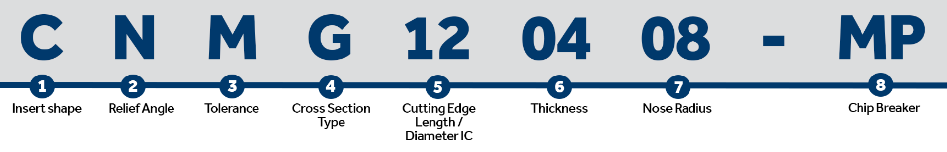
All turning inserts have a unique ISO code that contains various letters and numbers – believe it or not, these actually mean something! From just looking at the ISO code you can figure out the insert’s shape, relief angle, tolerance, cross-section type, cutting-edge length, thickness, radius, and chip breaker!
The thickness of a turning insert is measured from the bottom of the insert to the top of the cutting edge. This will be shown as a 2-digit number except where the insert features a T and then a single digit number eg T3. This is due to the fact that there are more than one increment within each mm. eg 03 is 3.18mm whereas T3 is thickest at 3.97mm.
Each member brings with them their own experience and know-how to add to our growing pool of technical knowledge. That’s why our services are known for being the best in the business!
It plays a crucial role in chip formation, tool life, cutting forces, and surface finish. Understanding the influence of the relief angle and selecting the appropriate one can greatly enhance machining performance, productivity, and the quality of the finished product.
Milling insertspecification
Important: The spring-loaded plastic part serves as the ball bearing brake and must sit on the copying ring. Adjust the required routing depth by rotating the black ring above the router table. Finally, connect a mobile dust extractor to the edge router.
It is a 2-digit number that generally indicates the width or length, however this is only applicable to insert shapes with no IC (inscribed circle), such as rectangular and parallelograms.
ISOinsertnomenclature pdf
To round the wooden edges, the tool can be used horizontally or vertically on the workpiece. When chamfering wood edges, make sure that the router is always securely seated in order to obtain an even and constant result.
Attach the workpiece to a stable base, e.g. the MFT multifunction table, in order to chamfer the wood edges. Secure the workpiece so that the edges can be processed with ease. For example, the Festool vacuum clamping system – the VAC SYS – is suitable for this. It can be secured to the MFT via an adapter plate. To chamfer edges, the workpiece can also be swivelled and easily brought into the required position via a rotation mechanism.
Insert the desired router bit into the OFK 500. Then fasten the acrylic glass dust extraction attachment using the clamping screw.
Whether in the workshop, on the construction site or at home – with Festool Connected, we offer you intelligent products and smart apps that can optimally support you in every work situation.
Carbide insertidentification chart PDF
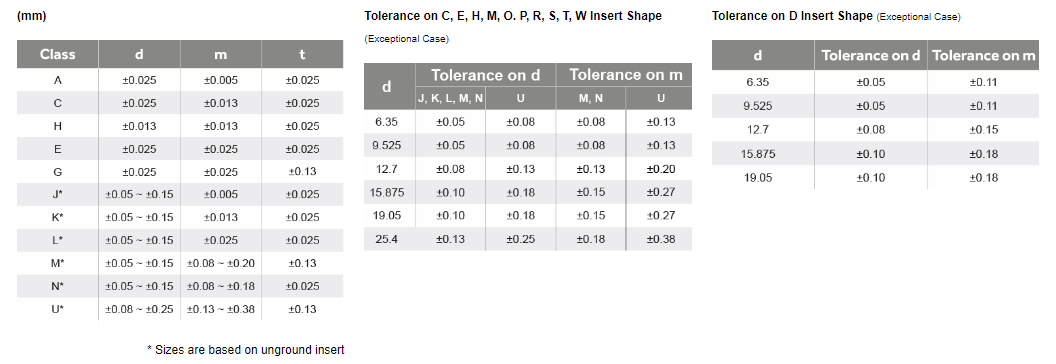
Tolerance dimensions are indicated by a letter ranging from A - U. Dimension A relates to the inscribed circle (IC), dimension B relates to the insert height (for pentagon, triangle, and trigon shapes – for other polygons, the dimension B relates to the distance that is measured along the bisector of the corner angle) and dimension T relates to the thickness of the insert.
The chip breaker is represented as 2 letters in the ISO code. The chip breaker affects the cutting resistance, if the cutting resistance is low, it can avoid chipping and fracturing of the cutting edges. Reduced cutting resistance can also decrease the tool load and heat built up. The chip breaker also determines the depth of cut the insert can take, if you are not applying the correct depth of cut then you won’t be activating the chip breaker, this can cause the swarf to build up and become stringy, some people refer to this as a bird’s nest.
ISO turninginsertnomenclature
Carbide insertcodes explained
Some of the below chipbreakers are available on both negative and positive inserts but the min-max depths of cut may vary.
In this blog, we will discuss how to identify all these key dimensions, so you will never need to check for part numbers again.
Carbide insertmaterial chart
The relief angle for a milling insert is of paramount importance in achieving efficient and successful machining operations.
ISOinsertgrade chart
The nose radius of an insert can affect the performance. A larger nose radius can result in the use of higher feed rates, and larger depths of cut, and they can handle more pressure, making them much better for heavier metal removal. Whereas a turning insert with a smaller nose radius can only take smaller depths of cut, they also have weaker cutting edges, and they can only handle a small amount of vibration but are much better for finishing as they are sharper and have less surface contact.
The cross-section highlights the differences in the design of the insert, such as the fixing holes, countersinks, and special features. This dictates what clamping method would be used to fix the insert on to the tool holder.
Choosing the right insert shape for your turning tool is essential. The shape of the insert can affect the vibration during operation, the ability to turn complex contours, the strength of the insert and its ability to take bigger and heavier cuts.
Switch on the edge router near to the workpiece to chamfer the edges. Guide the tool flush along the edge and rout the required profile in the opposite direction. To prevent burn marks, evenly go along the edge up to the end of the workpiece and then switch the tool off again after routing the edge.
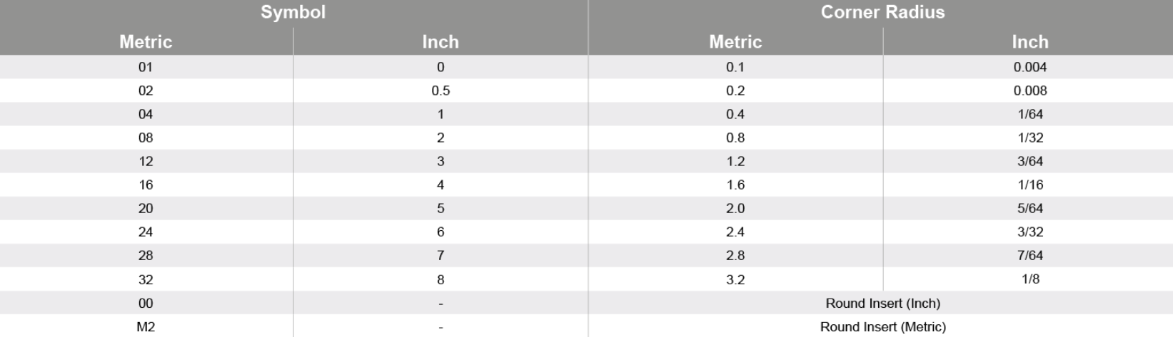
For insert shapes such as round, square, triangle & trigon, this would then indicate the diameter of the inscribed circle (IC).
Our illustrated guides and work results are documented working steps that we have performed in practice. They are individual examples and do not guarantee or promise that users will obtain the same results. The results will depend on the user's experience and skill, as well as the material being used. Illustrated guides do not replace any Festool operating manuals and/or safety instructions. Liability for ensuring that the information, instructions and applications are free from content defects and defects of title, in particular with regard to the absence of defects, correctness, freedom from third party intellectual property rights and copyrights, completeness and fitness for purpose, is excluded. Claims for damages made by the user, regardless of their legal basis, are excluded. These liability exclusions are not applicable if the damage was intentional or caused by gross negligence, or in cases of statutory liability. We cannot accept liability for damage resulting from defects.↑
Insert the desired router bit into the OFK 500. Then fasten the acrylic glass dust extraction attachment using the clamping screw. Important: The spring-loaded plastic part serves as the ball bearing brake and must sit on the copying ring. Adjust the required routing depth by rotating the black ring above the router table. Finally, connect a mobile dust extractor to the edge router.


 0086-813-8127573