
Why You Should Choose Coarse Thread Bolts Over Fine ... - coarse vs fine
Please feel free to contact us about sensors for milling machines. We also offer consultation for equipment-specific design.Our experienced engineers will be more than happy to assist you.
Lathe turning speeds and feedschart
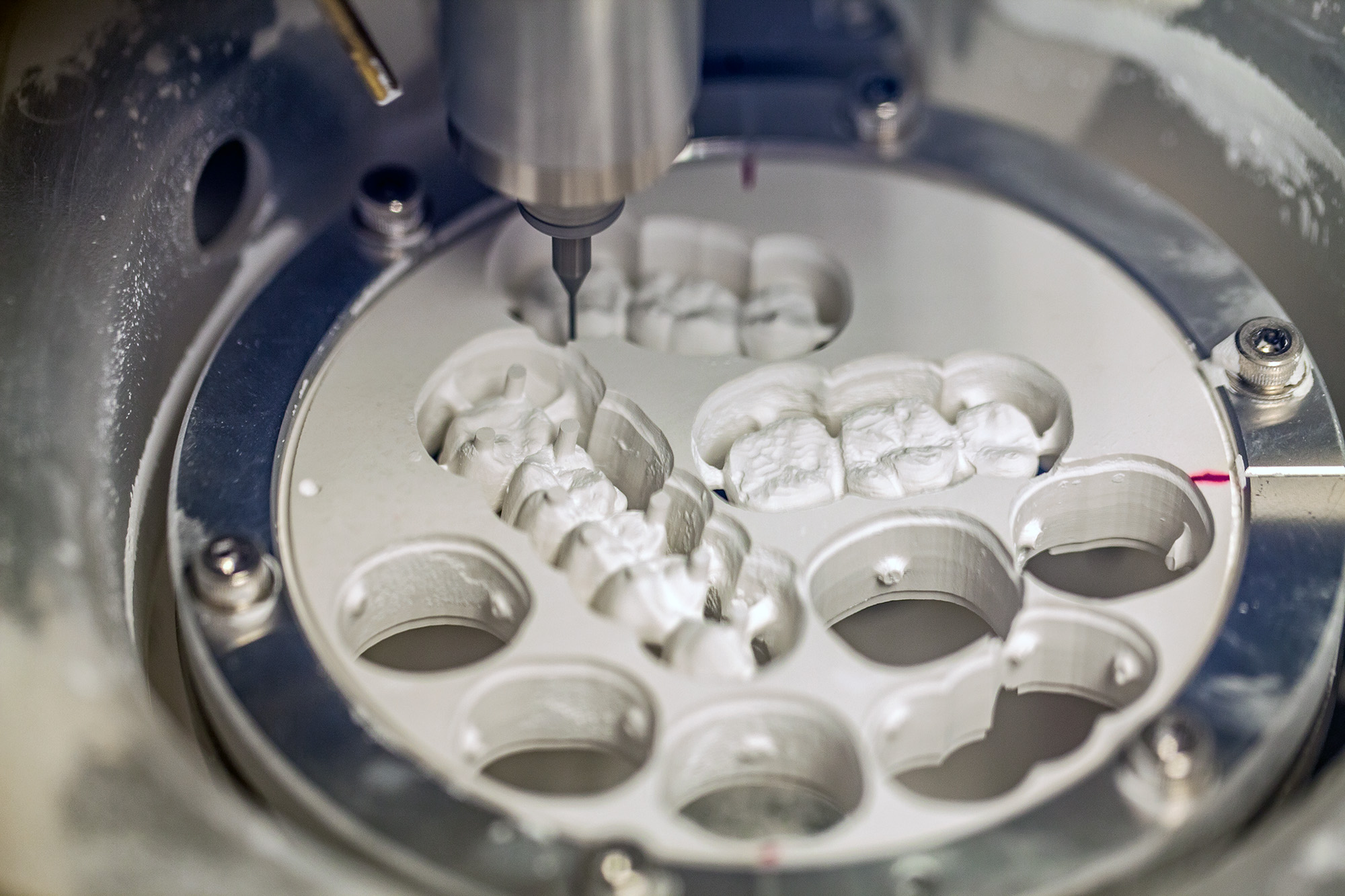
Since the bite and appearance of teeth greatly affect our daily lives, milling machines are required to have high machining accuracy.However, the accuracy of the milling machine itself is not enough for precision processing.Two essential prerequisites for maintaining machining accuracy are accurate "originating the tool/home positioning," and "workpiece positioning".
Lathe turning speeds and feedschart pdf
The challenges and solutions for dental milling machines will be addressed here. This is a must-read for those who are considering purchasing equipment and for designers of milling machine.
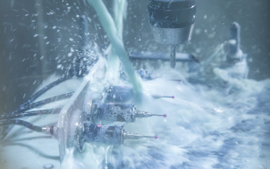
This is a method in which water or coolant is applied during processing to suppress frictional heat while polishing.It is mainly applied to process hard materials (e.g., glass-ceramic and titanium). Harder materials are increasingly in demand by patients due to their strength and aesthetic appearance.
Lathe turning speeds and feedstable
The touch probe is a sensor for originating the workpiece before machining and measuring dimensions after processing.By touching the workpiece (material) with a ball attached to the tip, it feeds back the "XYZ position coordinates, the origin of processing," to the milling machine. The K3S series of ultra-compact touch probes can be used for highly precise originating of workpieces even in small spaces, preventing machining defects caused by loosening or misalignment of the workpiece when it is set.
Lathe turning speeds and feedsformula
Our sensors are highly durable against water, oil, and chips.The sensor has passed strict water and oil resistance tests and has been used in many large machine tools. They demonstrate durability against water jets and coolant from all directions. The sensor body is designed for protection against water and dust with IP67-68 specifications, making it ideal for milling machines.
This is a dual-use model that is compatible with both dry and wet methods.While it has the advantage of being able to process a variety of materials with a single machine, it has the disadvantage of incurring non-productive time when switching from wet processing to dry processing, such as when cleaning and drying the machine.Other common disadvantages generally mentioned for having both functions are inadequate processing capabilities and high initial investment.
Metriclathe turning speeds and feeds
The workpiece must be held firmly so that it will not move during machining.If a disc is machined with a loose fixture, even with high accuracy of equipment, an error* will occur in the dimensions of the finished product, resulting in defective machining. This becomes especially important in unattended operation with a disc changer not monitored by a person.
This is a method that does not use water or coolant during processing. Small-diameter tools in the 0.5mm range can be used to cut mainly soft materials (zirconia, resin, PMMA, etc.), enabling fine modeling and processing. On the other hand, when cutting hard materials, small-diameter tools are not often used due to disadvantages such as breakage and longer machining time.
A dental milling machine is a small cutting machine that uses a CAD/CAM system.The program automatically processes "prosthetics" such as fillings and crowns to replace missing teeth. A disk-shaped dental material called a "disc" is cut into the shape of a tooth using a tool (i.e., milling bar). There are various types of disk materials, including non-metallic zirconia, ceramic, wax, and PMMA (acrylic resin), and metals such as titanium and cobalt. Each material has its own characteristics, such as resistance to discoloration and deterioration, and a beautiful finish, and is used according to its purpose.
The following is a partial list of dental milling machine manufacturers.Many European milling machines are distributed in Japan, but Japanese milling machine makers have also emerged in recent years.
*Coolant and dust can adhere if left unattended, leading to problems such as sensor malfunctions and tools sticking to the holder, so measures such as cleaning are necessary after use.
As a solution to the "tool originating" and "workpiece positioning" problems described above, we are pleased to introduce the following METROL sensors, already used in many milling machines.
Lathe turning speeds and feedspdf
In some cases, production efficiency is higher with dedicated machines that specialize in dry or wet processing respectively, so it cannot be generalized to say that a dual-use model is better. It is important to use the three methods according to the purpose, such as material characteristics and frequency of use.
There are three types of milling machines: dry, wet, and combination dry/wet models.The following is an overview of each type.
It refers to determining the starting point of tool machining. Milling machines use ultra-fine tools with a diameter of 1mm or less to process hard materials, which causes wear. Machining with unexpected wear or chipping on the tool can lead directly to machining defects due to dimensional deviations in the finished product. Especially when machining continuously, it is necessary to check each time.
Turning speeds and feedscalculator
Sensors can also be designed specifically for the operating environment of the milling machine.All METROL sensors are designed and manufactured at our own facility in Tokyo.Sensor size, contact-probe/surface diameter, stroke, air blow (to avoid chips), contact force, and sensor protection specifications can be customized to match the intended tool, available space, and sensor mounting location. Based on our extensive experience with milling machines, we will propose the optimum sensor for your operating conditions.
Lathe turning speeds and feedscalculator
If a sensor is damaged, the equipment cannot be used until it is restored, so the sensor must also be durable.Especially, the inside of a milling machine, whether dry or wet, is an adverse environment where fine chips and liquids scatter, and sensors with weak protection structures are at high risk of penetration into the main body and damage. Non-contact laser sensors and proximity sensors are not suitable for installation due to the high risk of failure caused by flying debris.
By physically contacting the tool, the tool setter sensor communicates the machining origin of the tool, which becomes the machining reference, to the machine control. METROL’s compact tool setter “P series” is highly precise and compact, with a repeatability of 0.5µm. Even minute dimensional errors caused by tool wear and chipping are compensated reliably to prevent machining defects. This is indispensable for avoiding problems such as continued machining defects during auto-operation. Because of its low cost, it has been applied by many milling machine manufacturers in Japan and across Europe.
There is a problem of not having enough space for sensor mounting.Many dental milling machines are small (desktop size) but designed to accommodate more milling bars, so sensor mounting space is limited. So, a compact sensor that can be mounted in a limited space is required.
Currently, there is a shortage of dental technicians and their work style. One in three people in Japan (more than 30 million people) use dentures, and there are 20,000 dental laboratories that make and repair these prosthetics, about the same number as public elementary schools.In the near future, Japan will inevitably see an increase in the population requiring prosthetics due to its aging population. However, it has been pointed out that the background of income and working environment of dental technicians is a factor in the shortage of technicians.As the demand for dental care increases in an aging society, the workload of dental technicians is expected to increase as well. Milling machines, which automate the processing of prosthetics and reduce the workload of technicians, will undoubtedly be one of the equipment most in demand in the future.This section describes the different types of milling machines and the challenges it poses.
Note: Speeds and Feeds are only general starting points and may vary depending on specific applications. MILLING Working Material Application Cutting Speed fpm Cutting Speed m/min Chip Load ipt Chip Load mm/t ALUMINUM Aluminum (5–8% Si) (356, 308, 242, 208) Rough Milling 2000–5000 610–1525 0.010–0.020 0.254–0.508 Aluminum (5–8% Si) (356, 308, 242, 208) Finish Milling 2000–6000 610–1830 0.005–0.010 0.127–0.254 Aluminum Cast (8–12% Si) (354, 357, 380) Rough Milling 1500–4000 460–1220 0.007–0.015 0.178–0.381 Aluminum Cast (8–12% Si) (354, 357, 380) Finish Milling 1500–5000 460–1525 0.004–0.008 0.102–0.204 Aluminum Cast (12–18% Si) (390) Rough Milling 1000–2000 305–610 0.005–0.010 0.127–0.254 Aluminum Cast (12–18% Si) (390) Finish Milling 1000–3000 305–915 0.002–0.006 0.050–0.150 OTHER MATERIALS Babbitt Milling 700–1100 210–335 0.003–0.010 0.076–0.254 Brass Milling 2000–4000 610–1220 0.001–0.008 0.025–0.200 Bronze Milling 900–1350 275–410 0.003–0.008 0.076–0.200 Carbon Milling 500–2000 150–610 0.0003–0.012 0.008–0.305 Carbon Fiber Materials Milling 500–2000 150–610 0.003–0.015 0.076–0.381 Copper Milling 750–1500 230–460 0.001–0.008 0.025–0.200 Glass Fiber Material Milling 750–1500 230–460 0.001–0.010 0.025–0.254 Green Ceramic Materials Milling 500–1500 150–460 0.002–0.010 0.050–0.254 Unfilled Plastic Milling 1000–4000 305–1220 0.003–0.020 0.076–0.508 Wood Milling 3300–9800 1000–3000 0.004–0.030 0.102–0.762 TURNING Working Material Application Cutting Speed fpm Cutting Speed m/min Chip Load ipt Chip Load mm/t ALUMINUM Aluminum (5–8% Si) (356, 308, 242, 208) Rough Turning 2000–5000 610–1525 0.010–0.025 0.254–0.635 Aluminum (5–8% Si) (356, 308, 242, 208) Finish Turning 2000–6000 610–1830 0.005–0.010 0.127–0.254 Aluminum Cast (8–12% Si) (354, 357, 380) Rough Turning 1500–4000 460–1220 0.007–0.020 0.178–0.508 Aluminum Cast (8–12% Si) (354, 357, 380) Finish Turning 1500–5000 460–1525 0.004–0.008 0.102–0.204 Aluminum Cast (12–18% Si) (390) Rough Turning 1000–2000 305–610 0.005–0.010 0.127–0.254 Aluminum Cast (12–18% Si) (390) Finish Turning 1000–3000 305–915 0.002–0.006 0.050–0.150 OTHER MATERIALS Babbitt Turning 700–1100 210–335 0.003–0.010 0.076–0.254 Brass Turning 2000–4000 610–1220 0.003–0.015 0.076–0.381 Bronze Turning 900–1350 275–410 0.003–0.010 0.076–0.254 Carbon Turning 500–2000 150–610 0.005–0.015 0.127–0.381 Carbon Fiber Materials Turning 500–2000 150–610 0.003–0.020 0.076–0.508 Copper Turning 750–1500 230–460 0.003–0.010 0.076–0.254 Glass Fiber Material Turning 750–1500 230–460 0.001–0.015 0.025–0.381 Green Ceramic Materials Turning 500–1500 150–460 0.002–0.020 0.050–0.508 Unfilled Plastic Turning 1000–4000 305–1220 0.003–0.020 0.076–0.508 Wood Turning 3300–9800 1000–3000 0.004–0.030 0.102–0.762 DRILLING Working Material Application Cutting Speedfpm Cutting Speedm/min Chip Loadipt Chip Loadmm/t ALUMINUM Aluminum(5–8% Si) (356, 308, 242, 208) Drilling 2000–6000 610–1830 0.001–0.010 0.025–0.254 Aluminum Cast(8–12% Si) (354, 357, 380) Drilling 1500–5000 460–1525 0.001–0.010 0.025–0.254 Aluminum Cast(12–18% Si) (390) Drilling 1000–3000 305–915 0.001–0.010 0.025–0.254 OTHER MATERIALS Babbitt Drilling 700–1100 210–335 0.001–0.010 0.025–0.254 Brass Drilling 2000–4000 610–1220 0.001–0.010 0.025–0.254 Bronze Drilling 900–1350 275–410 0.001–0.010 0.025–0.254 Carbon Drilling 500–2000 150–610 0.001–0.010 0.025–0.254 Carbon Fiber Materials Drilling 500–2000 150–610 0.001–0.010 0.025–0.254 Copper Drilling 750–1500 230–460 0.001–0.010 0.025–0.254 Glass Fiber Material Drilling 750–1500 230–460 0.001–0.010 0.025–0.254 Green Ceramic Materials Drilling 500–1500 150–460 0.001–0.010 0.025–0.254 Unfilled Plastic Drilling 1000–4000 305–1220 0.001–0.010 0.025–0.254 Wood Drilling 3300–9800 1000–3000 0.003–0.025 0.076–0.635


 0086-813-8127573