
Wordscapes Level 17219 Answers - Melt 3, Master - 17219
For turning applications, we do not need this formula since Spindle Speed is usually given in Constant Surface Speed (CSS), which uses SFM value directly. But if you still want to use the RPM formula, then the diameter value is the actual diameter of the workpiece.
The presence of slight errors in the machine does not necessarily mean that floating holders must be used. It must be remembered that the looseness in the machine plus the flexibility in the shank of the reamer provide some float. Also, on some types of machines, it is comparatively simple to insert black bushings in the tool holder and rebore them from the headstock. On other machines, adjustable rather than floating holders may be used.
Such a float allows the reamer to tilt slightly, but does not permit the shank of the reamer to move up or down or sideways. It will be noted that as the reamer feeds into the work the pressure will build up on the lower flute as before, still causing oversize and torn holes.
It should be realized, however, that reamers with a high left-hand spiral and right-hand cut tend to crowd the chips ahead of themselves. For this reason this design is not usually satisfactory for blind holes. For such holes, roughing reamers are often made of flat construction with little or no spiral angle.
In all hand reaming done by any of the methods described, with solid, expansion, or adjustable reamers, the reamer should never be rotated backwards to remove it from the hole. For this results in premature dulling of the reamer. If possible, it should be passed on through the hole and removed from the far side without stopping the rotation. If this is not possible, it should be withdrawn without stopping the forward rotation.
In particular, generous size and material specification should give good working life to areas subject to abrasive wear and work hardening under impact loads. But chatter, packed chips, or binding due to set-up misalignment can multiply normal operating forces many times. Tool failure, mechanical malfunctions, and operating errors threaten destructive casualties.
For reaming tapered holes with larger tapers, better results are obtained by first rough reaming the taper, followed by a finish taper ream to merely size and smooth the hole. In general, roughing reamers are made with fewer number of flutes than the finish reamers, and are of different construction as to hand of helix and degree of spiral. Quite often it is also necessary to use chip breakers ground in the cutting edges of the roughing reamer, usually in the form of a coarse pitch square thread.
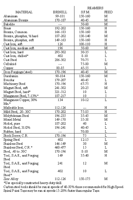
If experience with work material is lacking, it is best to start at the lowest cutting speed shown for that material and gradually increase speed until best results are obtained.
Climb cutting where and when possible will permit cutting speeds in the higher ranges and will also extend end mill life.
The usual practice is to ream from 0.004" to 0.012" on diameter (e.g. 0.002" to 0.006" on a side) in finishing operations. Seldom does one ream over 0.012".
Free CNC Speed and Feed Calculator and Formula The Speed and Feed calculator allows machinists and programmers to calculate cutting parameters for multiple materials and cutting tool types. You can also calculate Speeds and Feeds using Online FSWizard Widget right here: This free speed and feed calculator allows CNC Machinists and Programmers to calculate cutting parameters for a wide variety of materials and tools.FSWizard is the first and only online speed and feed calculator to consider dozens of variables when calculating Milling, Drilling and Turning Speeds and Feeds. Key features of FSWizard CNC Machinist Speed and Feed Calculator Built-in material and tool database (Check here for a list of materials available in the PRO version: Supported Materials) Materials ranging from Mild and tool steels to Stainless, Aluminum, and Plastics Speeds and Feeds all kinds of Machining operations. Supports Milling, Drilling, Tapping, and Turning tools Drilling Speed and Feed Calculator Milling Speed and Feed Calculator Turning and Tapping Speed and Feed Calculator Calculate Cutting Speed (SFM), Chip-Load (ipt), RPM, and Feed-Rate. Calculate required Machining Power Calculate optimal Depth and Width of Cut Calculate Chip Thinning and HSM(High-Speed Machining) Multiple free geometry calculators and reference charts under the MENU button Reference data for FHS, SHCS, Heli-Coil, Pipe Taps, Scientific Calculator, Bolt Hole, etc... Circular and Linear Bolt Hole Pattern Calculator Countersink and Center Drill Calculator ISO Fits and Tolerances Calculator How to calculate speeds and feeds using FSWizard CNC Machinist Speed and Feed Calculator Click on the Material button to select the work material Select the Tool Type drop-down to pick a proper tool for the job.Milling, Drilling, Tapping, and Turning tools are supported Then enter proper tool geometry and cutter engagement. Your results are displayed on the blue toolbar Click on the toolbar to get more insights about your cutting data. MENU button gives access to additional calculators and reference data! Please post your questions and suggestions on our support forums!
The usual line of reamers may be used in aluminum, but helical fluting is best for straight holes and spiral for tapered. Duplex taper reamers give splendid performances on precision work in this material. Extra care is needed to see that sufficient stock is left in the holes to give the reamers work to do. Otherwise burnishing will occur.
You may freely reproduce information presented herein without any consent from me, provided you include link to this site.In case when i am not the copyright holder, you may want to contact proper owner of material. Anyway, they are freely available on the Internet.If you hold the copyright right for any of the materials on this site and want them removed, please contact me here
© 2009-2022 Eldar Gerfanov. All Rights Reserved.© 2009 Eldar Gerfanov. Materials on this site are presented as is and are mostly for educational use.
Cutting Speed is the speed at which the tip of the tool travels through the material. It is commonly expressed in Surface Feet per Minute (SFM) or Surface Meters per Minute (SMM).
For either of these types of applications a rigid drive is satisfactory, because any misalignment of the machine spindle and the work tends to correct itself by means of the guiding bushings. By a rigid drive, we mean one where the reamer shank is help directly and rigidly in the machine spindle.
There are several means available to eliminate these torn, oversize holes. The first is to make corrections on the machine and tool holders. It is comparatively simple to make some of these corrections, such as cleaning tool holders, replacing worn sleeves or bushings, and relocating some times of tool holders. Others, such as correcting mis-indexing on a turret lathe or a multi-spindle automatic, may require a great deal of time.
When chips and end mill become discolored from heat, it is an indication of excessive cutting speed, which will result in premature damage to the tool.
It starts with knowing what workpiece material you have and what tooling and how you will be using to machine it.The combination of these two factors determines your initial Cutting Speed and Chip Load that you can put into the speed and feed formulas to calculate the cutting tool RPM and feed rate.
One sure way to overload a cutting tooth is to block the path of the chip flowing across its face so that the chip is re-cut. Chip breakers are frequently employed to curl an otherwise stringy chip so that it will break in the form of a figure nine and fall away. It is difficult to remove work materials like soft steel or copper alloys and titanium, whose chips tend to weld onto the tool face. Tool design should provide space for chip flow and means of disposal, which may well be the solution to many problems of tool chipping.
Because of the large amount of stock to be removed and the length of the cut, taper reamers are subjected to much greater torsional strains than the ordinary straight reamer that cuts on the end only. The tendency, therefore, is to chatter, with consequent poor finish or actual destruction of the reamer. The greater the taper, the worse these conditions will become.
Various types of floating drivers are in use, each possessing individual merits. Some types allow angular relation between the center lines of the driving spindle and the reamer. Others allow side movement of the axis of the reamer with that of the driving spindle with the two being parallel. Others combine these two features.
In cases where the work piece is small enough to be handled with ease, it is often advisable to place the reamer vertically in a vise and rotate the work down over the reamer by hand. If the work is quite light it may not have enough mass to dampen vibrations. In such cases a holding device for the work may be employed which will add weight to the part to be reamed. This holding device should have two opposite handles on it, large enough in diameter to permit a stead controlled torque.
If the selection of spindle speeds on the milling machine is so limited that it is impossible to run the end mill within the suggested range, then use whatever speed is available below the lowest in the range to prevent damage to the end mill.
The reaming of tapered holes has always presented a problem in reamer design and operation because of the very nature of the work to be performed. Usually one starts out with a drilled or bored hole of uniform diameter throughout. The diameter of this hole is slightly smaller than the finished diameter of the small end of the tapered hole to be produced.
Highly alloyed materials containing nickel, chromium, cobalt, molybdenum, tungsten, and such, necessitate low cutting speeds even though they are not considered hard.
When holes are to be located at exact distances from some point or some other hole, the only sure method is to do the reaming in jigs or fixtures. In such jigs or fixtures the work is located and held securely, and the reamer is guided in bushings set in exact relation to locating points in the work.
In order to overcome this condition it is sometimes necessary to grind back taper on the reamer. While the use of back taper on reamers will often eliminate these rough, oversize reamed holes, it must be remembered that this back taper reduces the reamer life, particularly on close tolerance holes. This special back taper varies between .001” and .005” per inch of flute.
The use of a conventional reamer held rigidly in such a machine quite often results in poor finish and oversize holes, particularly at the start of the hole. Such holes are usually called “bell-mouthed.”
The strength of each member can be considered separately and related to the magnitude and application of the forces it will transmit. It should clearly be sufficient to prevent breakage or deformation beyond the elastic limit when the operation is performed correctly. The designer must also consider overloads and damage that may be encountered, providing abundant strength wherever economically possible.
When a reaming fixture is light in weight then it's practical to use a rigid drive and allow it to “float” on the reaming table. If the fixture is heavy, it is recommended to use a floating holder drive to permit self-alignment.
In smaller sizes, especially those below ½", it's advisable to ream only 0.006" or 0.008" in diameter. This is relatively easy to arrange, as drill sizes come in smaller increments within this range.
In radial drill presses or in table presses equipped with sliding jigs, great care must be used. Sometimes bronze or fibre caps are placed over the bushings to act as a lead on device, but even this will not protect the reamer unless the tool is properly centered in the bushing.
Where conditions permit the use of carbide reamers, the speeds may often be increased over those recommended for HSS (high-speed steel) reamers. The limiting factor is usually an absence of rigidity in the setup. Any chatter, which is often caused by too high a speed, is likely to chip the cutting edges of a carbide reamer. Always select a speed that is slow enough to eliminate chatter. Close tolerances and fine finishes often require the use of considerably lower speeds than those recommended in Table H-5. The very high surface speeds which have been found necessary for turning operations with carbide tools present some difficulties if applied to reamers. In lathe work, the cutting tool may usually be made of any desired cross-section and held in a large rigid tool-post with minimum overhang. In reaming, however, hole size limits cross-section of the tool, and usually considerable overhang is required. Both result in a loss of the rigidity so necessary with very high surface speeds if chatter is to be avoided.
Higher production rates are possible with multiple-flute end mills since feed per tooth is multiplied by the number of teeth enabling a proportional increase in the feedrate.
CNCfeed rate calculator
The reamer should be rotated slowly and evenly, allowing it to align itself with the hole to be reamed. Wrenches should be large enough to permit a steady torque which will help to control vibration and chatter. The feed should be steady and large compared to the feed used in machine reamers. Feeds up to one quarter of the reamer diameter per revolution are not at all unusual.
It is almost universally accepted as good practice to design reamers of the solid, shell, or inserted-blade types with broken or irregular flute spacing. The purpose is to eliminate the liability to vibrate, or “chatter.” This is accomplished by a “broken” indexing when the flutes are milled before heat treatment and when sharpening in finishing and in service.
Machine way motion becomes jumpy at slow speeds (“slip-stick” motion), even when heavy lubrication. A milling cutter at slow feed may actually rub until pressure builds up. It then may dig into the work and surge ahead. Adding to the difficulty, the sudden change in cutting torque adds to the pounding caused be teeth entering the cut.
As drill sizes vary in increments of 1/64", it is found that theoretically 1/64" has been left for reaming, but in fact it is only 0.012", as most drills cut oversize by 0.002" to 0.004".
Torsional vibration and backlash tend to develop in a rotary drive train. Should cutter rotation become so erratic that it momentarily stops, carbide teeth will generally break at once by being bumped into the work. With some teeth gone, the entire cutter may fail progressively as each successive tooth is unable to carry the extra load left by the preceding damaged teeth.
Feed rateformula formilling
In cases where there is a large quantity of light parts to be reamed, the reamer is often mounted horizontally in a reaming machine. Most reaming machines are essentially chucks mounted on the output shaft of a motor-driven gear reducer. This drives the reamer at the necessary slow speed. The work piece is fed slowly and steadily over the reamer.
Taper Reamers must, therefore, be constructed as sturdily as possible. Cutting edges must be adequately backed up, and flutes must be sufficiently large, with well rounded bottoms.
However, the practice of using a reamer as a locating device and forcing it to drag the work over into alignment is not good, and is likely to result in excessive wear or chipped edges of the reamer.
Maximum end mill life cannot be realized if erratic hand-feeding methods are used that cause a variation in tooth load and which invariably leads to tooth corner chipping or breakage at tool shank. Controlled power feed is recommended.
Feed rate calculator millingmetric
Occasionally when the job conditions are such that a great deal of difficulty is experienced with chatter, or the holes are definitely out of round even though not chattered, it is necessary to employ a flute construction not generally used. This particular reamer construction embodies the use of an uneven or even number of flutes coupled with irregular flute spacing of the type that no two cutting edges are diametrically opposite each other. The reamers thereby are very difficult to measure for size and taper and their use, therefore, is to be avoided unless absolutely necessary.
Broken or uneven spacing is carefully planned to occur according to prescribed rules set down by the individual manufacturer to meet his own requirements. Starting with one flute at “zero” as basic, the second flute may be minus a definite number of degrees from even spacing, the third will be plus a similar number, the next minus a different number, the following will be plus still another number of degrees, and so on until “zero” is reached again.
This free speed and feed calculator allows CNC Machinists and Programmers to calculate cutting parameters for a wide variety of materials and tools.FSWizard is the first and only online speed and feed calculator to consider dozens of variables when calculating Milling, Drilling and Turning Speeds and Feeds.
Steelfeed rate calculator milling
When you have manufacturers' data simply find your tool in the catalog and cross-reference the cutting speed and chip load against the tool diameter:
Theoretically, in this type of reaming the axis of the reamer coincides with the axis of machine spindle, and no difficulty should be encountered. However, in actual practice, this condition seldom exists. It probably would be wise to assume that it never exists and to expect the presence of misalignment on jobs of this nature.
One of the primary tasks machinists must learn to perform is a calculation of speeds and feeds required for milling, drilling, and turning.
When reaming is done in any of the machines listed above, certain problems arise because the reamer is stationary and the work revolves. This is the opposite of the condition normally encountered in drill-machining press reaming.
No deflection can be allowed. Clearance, chamfer relief, and rake angles must be specified to suit the work to be done. If the Brinell reading is high, the heat treatment of the reamer must be correct when high-speed steel is used; and if the reading is above Brinell 415, it's recommended to go to carbide tipping.
Plain reaming should not be depended on to align a series of holes and center on them on a common axis, because it merely trues the diameter of the individual hole. Concentricity and alignment require line reaming, which requires that the holes be of equal or progressively smaller diameters to permit entrance and withdrawal of the reamers. Provision must be made for guiding the reamer bar or arbor at both ends.
The most usual means for holding and driving reamers is the three-jaw chuck. Another is the straight-sleeve and setscrew method. Taper shanks are sometimes flattened on one side and used in what is known as a “use-‘em-up” sleeve or socket. Reamers with adapters for quick-change chucks are used on production set-ups.
The spiral angle should be about 45 degrees and of a hand opposite to the direction of rotation. A greater spiral angle than this does not tend to improve the quality of the cut, but does materially increase the amount of end pressure required to feel the reamer into the work.
Increasing mass reduces vibration amplitude and resonant frequency, while dampening reduces amplitude by dissipating vibratory energy as frictional heat. Since each part of the cutting system (i.e. the machine, the fixture, the tool and the work piece) can affect the mode and amount of vibration most should be made oversize and broadly supported. This provides design latitude for those members having more severe costs and space limitations. Tools should be rigid for fast, efficient cuts.
The formula is used for milling and drilling applications. Please note that some tool manufacturers provide their recommended feed rate as feed per revolution. In such cases do not multiply by the number of teeth.
Feed rateformula
Since cutting speeds can be in either Imperial (SFM) or Metric (SMM or m/min) units, you have to use two formulas to calculate the RPM.
If the holes to be reamed are short, the reamer may be guided at the entering side of the hole only. The guide bushing then may be made to fit the outside diameter of the reamer flute.
Feeds in reaming are usually two to three times greater than those used for drilling. The amount of feed may vary with different materials, but a good starting point would be between .0015 and .004 inches per revolution. Too low a feed may “glaze” the hole, which has the result of work hardening the material, causing occasional chatter and excessive wear on the reamer. Too high a feed tends to reduce the accuracy of the hole and the quality of the surface finish.
If, on the other hand, the reamer is to guide itself into a previously made hole, a rigid drive is no longer satisfactory, because any existing misalignment of the machine spindle with the work will result in reamed holes that are
The ideal floating driver must be able to do both of these. In other words, it must be able to adjust itself to misalignment of both types and in all positions throughout its circle of rotation. The amount of permissible angular or parallel float should be adjusted to cover the greatest amount of misalignment that is likely to occur on any given job.
The most efficient cutting speed for machine reaming depends on the type of material being reamed, the amount of stock to be removed, the tool material being used, the finish required, and the rigidity of the setup. A good starting point, when machine reaming, is to use one-third to one-half of the cutting speed used for drilling the same materials. Table H-5 may be used as a guide.
These may be particularly necessary when the tapered hole is quite long and the taper relatively small. As an added precaution, the number of flutes in a finishing reamer should never be an even multiple of the number of flues in the roughing reamer nor the same number of flutes.
The second method is to use floating holders for reamers. There are many kinds and designs of floating holders. Some correct for angular error only. Some correct for a parallel misalignment only, while some correct for both. Besides varying in function and design, these different floating holders also vary in their inherent rigidity. The problem in such holders is to allow movement in certain directions while restricting it in others. Naturally, this is not accomplished in the same manner in all designs and the rigidity of different types of holders, whether floating or not, varies considerably.
As already emphasized, reamers do not work well when they chatter. Carbide Tipped Reamers in particular cannot stand even a momentary chatter at the start of a hole, as such a vibration is likely to chip the cutting edges.
Floating holders are almost a “must” on stainless, as they hold work hardening to a minimum. Carbide-tipped reamers improve the finish and last longer in stainless than high-speed.
Calculate Speeds and Feeds for 1/2" (0.5 in) 2 flute end mill in Mild Steel at cutting speed = 100(ft/min), Chip Load=0.001(inch per tooth)
Millingspeed andfeed Calculatorfree download
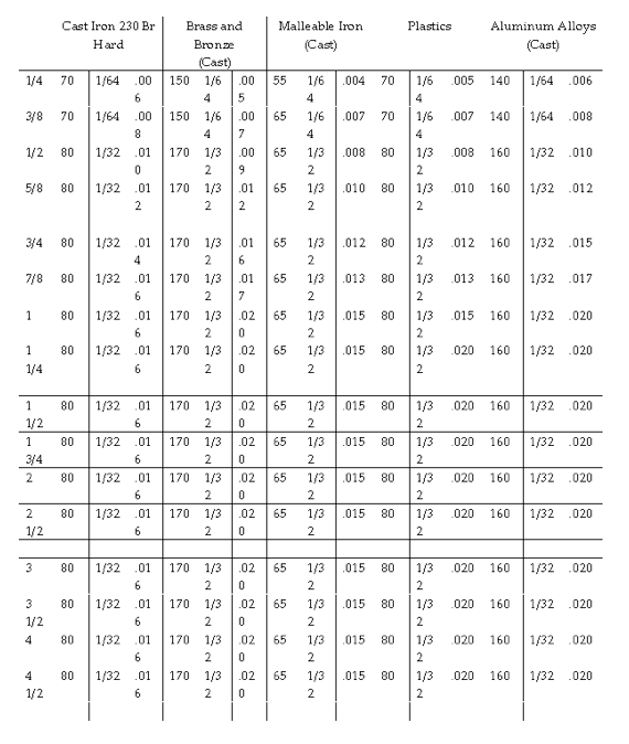
*The 1/32” stock removal allowance for reaming the Brass, Bronze, and Aluminum groups may be reduced to 1/64” drilled holes rather than cores holes. The Cast Iron group do not include the alloyed Cast Irons, as these require 10% to 20% slower speeds.
Tapers such as these are far in excess of the very slight taper which has been found best for stock reamers designed to do the average reaming job. The figure of .005”, in particular, seems excessive, and in the interest of economy the back taper should be kept as low as possible without interfering with the required hole size and finish.
The operation of taper reaming now consists of greatly enlarging one end of this hole, with this enlargement gradually decreasing towards the other end. This means that the Taper Reamer, instead of being a finishing tool, in reality becomes a tool for heavy stock removal, and further, that this tool at the finish of the operation is engaged in the cut throughout its length.
Longer tool life is obtained by operating in the lower cutting speeds with a generous feedrate per tooth when the diameter and length of end mill and set-up in general will permit.
Work hardening is often experienced in certain types of stainless steel and can be avoided only by helical fluting, narrow lands, a good secondary clearance, and omission of the usual concentric margin. Should a concentric margin be demanded, it ought to be kept to the width of a hair folicle.
This oversize condition is not always cured by the use of floating holders alone. In the case of a turret which has worn low, an attempt to correct this condition is made through the use of a simple pin drive float.
In the case of a reamer held at an angle to the spindle of the machine, as this reamer is fed into the work, the lower flute will bear harder and harder against the wall of the reamed hole. The results in a scraping action by this flute which causes an oversize hole. The pressure also quite often causes a building up on this flute. When the pressure gets too high, this built-up portion breaks loose, causing gouges and tears in the reamed surface.
Feed rate calculator millingformula
For this type of reaming the ideal arrangement is to guide the reamer on both sides of the work, especially if the hole is comparatively long. A special piloted reamer is required for this purpose. Guide bushings should fit snug to the pilots, but should not be so right they will seize and bind. Pilots should be grooved throughout their length. These grooves serve the double purpose of permitting the cutting fluid to lubricate the pilots and to scavenge any chips that tend to wedge between the pilots and bushings.
Good tool design is accomplished with consideration of many inseparably related factors: the comparison, hardness, condition, and shape of the work piece material; the rate and volume of the specified production; the type, motions, power, and speed of the machine tool to be used; the toolholders and workholders available or be designed; the specified accuracy and surface of the finished work piece, and many other factors, common or specific to the particular operation.
An end-cutting function can be given to any reamer by grinding the end off square with the axis as shown at A (Fig 15-5), removing the chamfer entirely. In effect, the tool cuts like an end mill. However, the desired results will not be obtained unless it is well guided and suitably supported – details that the designer should check.
For machine reaming, it has been found that a reamer having few flutes, and with cutting edges at a large spiral angle with the axis, is by far the best. Flutes may vary in number from two to five in the ordinary range of reamer sizes.
The range of cutting speed for each class of material is quite broad to allow for variables in each individual situation that could be compensated for by more or less cutting speed.
The Speed and Feed calculator allows machinists and programmers to calculate cutting parameters for multiple materials and cutting tool types.
Feeds and speedscalculatormetric
When cutting edges dull rapidly without tool or chip discoloration, it is an indication of a highly abrasive work piece or high resistance to chip separation, and cutting speed must be reduced.
Set-up rigidity is vital to the maintaining dimensional accuracy of the cut surface, since the tool shifts into or out of the cut with the accumulation of static deflections and take-up of loose fits. Rigidity also maintains surface-finish quality, avoiding the marks made by elastic vibration and free play of loose fits and backlash. In the control of vibration, rigidity of the part and cutting tool can make the difference between success and failure of the machining operation.
If the material is free cutting, any lightly constructed tool is adequate. If the material is hard, tough, stringy, or of work-hardening nature, careful attention is needed to choose a solid reamer or a rugged type of inserted-blade design.
When reamers must guide themselves into previously made holes, they require floating holders to maintain alignment and prevent tapered, out-of-round, and bellmouth holes. There are several types of floating holders, some of which permit an angular float; others permit a parallel float; still others permit both features.
When the work piece is reasonable rigid, hand reaming may be performed by rotating the reamer by means of a double end tap wrench applied to the driving square. This type of wrench, which permits a balanced drive, should always be used in preference to a single-end wrench. The use of single-end wrenches makes it almost impossible to apply torque without distributing the alignment of the reamer and the hole.
Another sure way to overload a cutting tooth is to increase the feed rate drastically beyond its structural or chip-disposal capacity. Machine structural deflection accomplishes this is the example of a drill breaking as it breaks through the work. As the heavy thrust of the chisel edge is relieved, structural members spring back toward their unstressed shape, and the drill lips plunge into the work for an oversize bite. Feed mechanisms may employ air or hydraulic fluid whose compression is elastic; or gearing and a leadscrew nut fit may introduce backlash.
The use of bushings as guides for reamers is of great help. The ideal job would employ a fixed jig and bushing with a rigid spindle and a minimum of overhang. It is particularly important when using bushings that the spindle be accurately aligned with the bushing in order to prevent the reamer from hitting the top of the hardened bushing.
In screw machines and turret lathes the reamer will always follow the bored or drilled hole; and if a rigid holder were used, a tapered or “bell-mouth” hole will form. Therefore, the proper style of floating holder must be specified and it must be “full” floating to allow the tool to adjust itself in directions freely and easily.
Occasionally the designer is confronted with the task of supplying a reamer for straightening holes that have run off from the true center line owing to irregularities in the subject piece, uneven conditions in the metal, or plain carelessness in the shop. When the errors are not too great, the job can be saved by substituting an end-cutting reamer for one with the conventional chamfer.
There are two principles that must be embodied in satisfactory floating reamer drivers. First is the angular positions that the reamer must be permitted to assume. Second is the parallel floating. Here, the reamer axis may move away from the spindle axis while the two are in parallel.
In actual practice both of these errors are often present at the same time in a single set-up. Such misalignment can be caused by a combination of several things:
The same problem arises if work is reamed on a table press without a bushing. The use of a short entering taped on the front of the reamer, or in some cases a shirt pilot section, may be of help in leading the reamer into the hole.
Better reaming usually results when the product is designed to facilitate that operation. Where possible, provision should be made for the reamer to pass through the work piece. This avoids the necessity for reaming a blind hole; when this is unavoidable, the depth of cut should be controlled to prevent bottoming and probably damaging the reamer. A reamer should enter a hole at right angles to the work surface to permit all teeth to engage for a good start, because reaming at an angle makes it to turn out good work.
It should be remembered that high-spiral Taper Reamers cannot be used on hand operations because of the end pressure required, but for machine operations this is by far outweighed by smoothness of operation, better quality of work, and longer reamer life. For hand operation, Taper Reamers with straight flutes, or with about ten degrees of spiral opposite in direction to that of the cut, are recommended.


 0086-813-8127573