
ZIP Code 24531 - Chatham Virginia - 24531 zip code
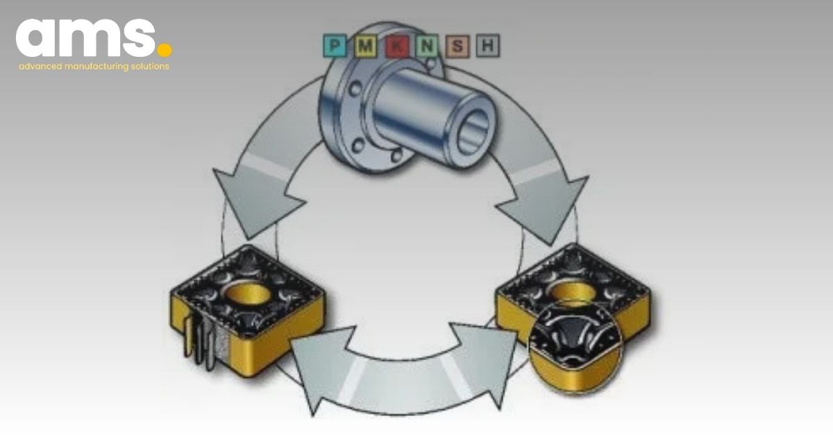
Critical factors in metal machining encompass machining components such as ISO P, M, K, N, S, H, the machining application (counting, semi-finishing, roughing), and machining conditions (good, average, difficult). Additionally, the insert's geometric design and backing layer are crucial, as they have the potential to complement each other. For instance, sturdy backing layers can address shortcomings in the stability of the insert's geometric design.
Grinding Wheel SpeedCalculator - Metric Units Enter in metric units. Millimeters (mm) for wheel diameter,Meters per second (MPS) for surface speed.
Generally, opting for a nose radius RE equal to or smaller than the cutting depth Ap will yield optimal efficiency in the machining process.
The connection between the tool nose radius and depth of cut (D.O.C.) greatly impacts vibration during machining. As the depth of cut increases, radial forces can displace the insert from the cutting surface and lead to axial pressure.
TurningTool Holder
To differentiate between single-sided and double-sided inserts, one can observe the second character in the insert product code. If the letter N is present, it indicates a double-sided insert, whereas the absence of the letter N denotes a single-sided insert.
Cermet inserts
Alloy turning inserts feature a securely welded structure, delivering exceptional reliability and instilling confidence in their use. Users select the suitable cutting tool and meticulously execute the welding process to affix it to the tool holder, adhering to stringent technical specifications, ultimately ensuring exceptional durability in practical applications.
The selection of materials for crafting turning tools is contingent upon the turning speed. For low turning speeds, materials with good hardness and wear resistance are imperative. Conversely, high turning speeds necessitate materials with robust heat resistance, high hardness, and superior durability. Hence, the process of material selection for producing turning tools significantly influences the performance and quality of the turning procedure.
Of particular interest to many individuals is the clearance angle of the insert (turning tool). The primary distinction between single-sided inserts (positive inserts) and double-sided inserts (negative inserts) lies in the chip release angle. Single-sided inserts feature chip release angles ranging from 1° to 90°, while double-sided inserts are characterized by either no chip release angle or a chip release angle of 0°.
Choosing the right tool nose radius and depth of cut has a significant impact on machining performance. Sandvik Coromant's expertise in this area ensures that the relationship between tool nose radius and depth of cut is optimized for minimal vibration and superior surface quality. Their high precision inserts are engineered to minimize vibration phenomena and improve surface quality post-machining.
A double-sided insert (negative insert) is constructed with a 0° chip release angle, whereas a single-sided insert (positive insert) features a chip release angle of less than 90°. Images demonstrating the positive and negative insert types showcase their assembly into the toolholder and their respective contact angle with the workpiece.
The cutting force is focused towards the workpiece clamp, reducing vibration tendencies and enhancing shoulder turning capabilities. However, this also results in higher cutting forces and greater vulnerability to wear when machining workpieces like heat-resistant super alloys and post-heat-treated steel.
1. Rough turning: Utilized for cutting processes involving substantial depth (D.O.C) and high feed rates, necessitating inserts with the most rigid cutting angle design.
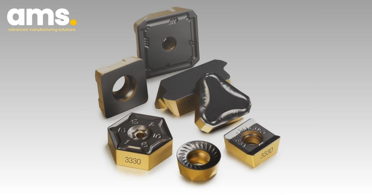
In the metalworking industry, cutting tools play a crucial role in operations such as turning, boring, drilling, and other cutting procedures. The use of inserts (chips) is categorized into different types, coatings, and geometric shapes.
To mitigate vibration and enhance surface quality post-machining, prioritizing impact force in the axial direction over radial force is essential.
Turninginserts
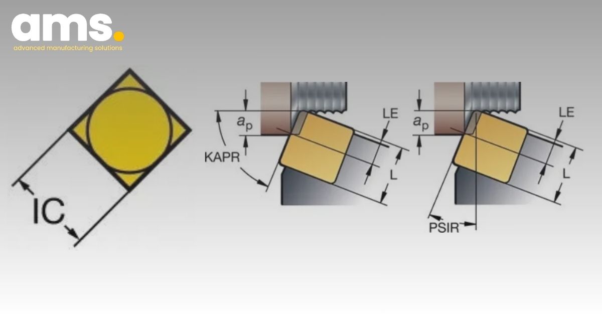
The corner radius of the cutting tool (RE) is a crucial factor in lathe operations. The selection of nose radius sizes, like 0.2 - 0.4 - 0.8 in inserts, is significant, and the determination depends on various elements such as depth of cut (D.O.C), feed rate, surface finish
Tungaloy inserts catalog
All cutting tools come with Positive Inserts (Single-sided turning tools) and Negative Inserts (2-sided turning tools), offering versatility and a range of options for milling, turning, and drilling applications in the mechanical industry, ensuring precision.
Sandvik Coromant's inserts are specifically engineered to concentrate cutting forces towards the workpiece clamp, reducing vibration tendencies and improving machining capabilities. However, their inserts are also designed to address the challenges of machining workpieces such as heat-resistant super alloys and post-heat-treated steel, offering solutions to minimize tool wear and enhance overall productivity.
ID grooveinsert
Roundinsert turningtool
The selection of insert shape is connected to the capability to attain the necessary cutting angle for the machining tool. Opting for the largest possible tip angle ensures the robustness and dependability of the cutting head, although this must be deliberated according to the distinct demands of the machining process, as it may not always be the most suitable choice.
Choosing the size of the insert depends on the particular requirements of the application and the spatial constraints for the cutting tool in operation. Opting for larger insert sizes can enhance stability during machining. For heavy machining tasks like roughing, insert sizes typically exceed IC by 25 mm (1 inch). Conversely, in finishing turning, reducing the insert size is often suitable to meet the specific needs of the machining process.
Sandvik Coromant's inserts, including their alloy turning inserts, are known for their securely welded structure, providing exceptional reliability and confidence in use. These inserts are meticulously designed to cater to various machining applications, such as rough turning, semi-finished turning, and finishing turning. The robust design and high-quality construction of these inserts make them well-suited for a wide range of metal cutting tasks.
Finishing turning: Employed for cutting processes with minimal D.O.C and feed rates, while requiring minimal cutting force.
For over 20 years, AMS Company Limited has been the trusted distributor of Sandvik Coromant products in Vietnam, catering to the precise needs of the mechanical industry. With a wealth of experience and a commitment to quality, AMS Company Limited stands as the premier source for accessing the full range of Sandvik Coromant's precision cutting tools and inserts. Whether you're seeking cutting-edge solutions for your machining operations or expert advice on tool selection, AMS Company Limited is your reliable partner for excellence in precision mechanical applications.
CBNTurninginserts
The materials utilized in manufacturing turning inserts encompass a broad spectrum, ranging from alloy steel, carbon steel, high-speed steel, ceramic metal to hard alloy. Each material type has specific requirements for heat resistance, hardness, durability, and abrasion resistance, all of which must be meticulously met.
Turning inserts, crucial components in the turning procedure, are vital for shaping details on the lathe (CNC lathe). Available in various shapes and sizes, these inserts are crafted from alloy, showcasing exceptional sharpness and precision during material cutting. By affixing to the cutting tool, turning inserts enhance its sharpness and accuracy, facilitating machinists in working with diverse materials of varying hardness.
Understanding the contact angle and lead angle in machining is crucial for achieving optimal results. Sandvik Coromant's inserts are designed to address the complexities associated with contact angle and lead angle, ensuring that the shape of the workpiece, cutting forces, and tool lifespan are all carefully considered and optimized for superior machining outcomes.
In the process of selecting chip inserts, numerous factors influence the quality of the finished product. Therefore, meticulous consideration of the geometric design, support, form, insert size, blade angle, and insert contact angle is crucial in achieving optimal chip control during machining.
The radial increase in cutting forces when interacting with the workpiece can lead to vibration while simultaneously diminishing the primary cutting force. When machining thin and flexible workpieces, increasing the feed speeds can be adjusted to minimize chip breaking and diminish tool wear. However, in this scenario, it is not feasible to turn the shoulder at a 90° angle.
Alloy turning inserts with screw fastening are designed to be secured in place using screws, offering users the flexibility to swiftly replace inserts as needed. This feature proves especially advantageous when worn inserts result from prolonged cutting of tough materials. Through simple re-sharpening and reinsertion, the turning insert can be seamlessly reinstated for continued effective use.
Furthermore, Sandvik Coromant offers a variety of insert types, including double-sided (negative) inserts and single-sided (positive) inserts. Each type has specific chip release angles and assembly configurations, illustrating the company's commitment to precision and versatility in metal cutting applications.
The contact angle KAPR, also known as the Lead PISR angle, refers to the angle formed between the cutting edge and the feed direction. Selecting the appropriate entry/lead angle is crucial for the effectiveness of the machining process. Both the contact angle KAPR and lead angle PISR influence the workpiece shape, the direction of cutting force, and the length of the cutting edge during machining.
Tungaloyinsertgrades
Employing inserts with substantial nose angles necessitates support from more robust equipment and can result in heightened vibration compared to using inserts with smaller nose angles. Conversely, inserts with a diminutive nose angle may be less robust and feature a limited cutting angle, thereby increasing susceptibility to temperature effects during machining.
Grinding Wheel Speed Calculator - British Units CALCULATING SFPM The performance of grinding wheels and quality of the finished workpiece is affected by how fast the abrasive grains sweep over the workpiece. That speed affects surface quality, workpiece burn, material removal rates, and other factors. Since the speed of the abrasives on the wheel perimeter depends upon the diameter of the wheel, RPM isn't a useful measure. To calculate the speed, consider that abrasive grains on the wheel perimeter traverse the circumference of the wheel once for every revolution of the wheel. So their speed is equal to the circumference (in feet) times the number revolutions per minute(RPM). Also important is pi,a constant ratio between diameter and circumference of a circle. In the boxes on the left enter two values to calculate a third value. One of the three boxes must be blank. Wheel diameter is measured in inches for US/English Units and in mm for Metric.


 0086-813-8127573