
Zwilling - Twin Master 6" Stainless Steel Boning Knife - 32231
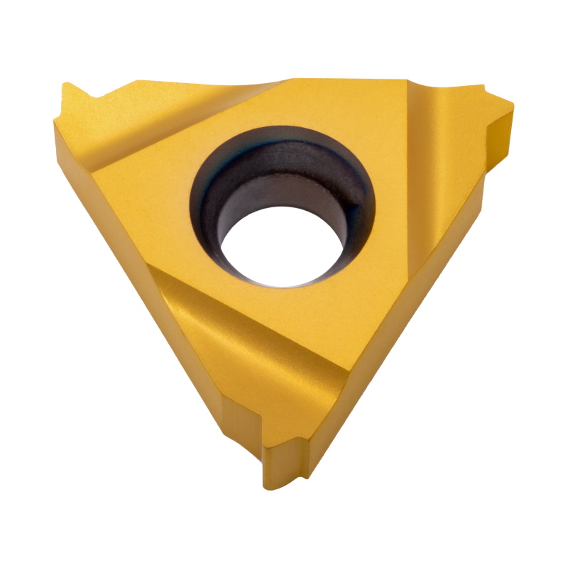
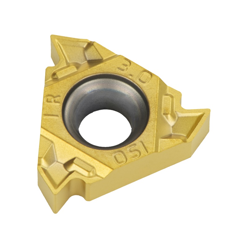
Sintered thread turning inserts with a chip breaker, designed for excellent performance in a wide range of materials. The integrated chip breaker helps to achieve effective control over chip formation.
In order to compare the solution developed in this post for 2D tolerance stack up, the following picture shown the result shown from the original maker for this case study (See requirement 3).
Typically, one would consider using such a tool holder in case of a large-pitch thread with a relatively small diameter.
Monte-Carlo (MC) tolerance stack-up analysis is a way to check if parts will fit together correctly in a product. It uses a statistical approach to account for variations that might occur due to design tolerances. Basically, it creates a chain of calculations using matrices to see how these variations might impact the final assembly feature. To do this, it assumes that the variations follow a normal distribution, also called a Gaussian distribution.
Threading insertsize chart
The case study is the R-A assembly (see pictures bellow); it consists of two nominally parallel shafts (Item 3) mounted into a housing (Item 1). During assembly, the bushings (Item 2) have a slight interference fit with the holes of the housing and a small amount of clearance with the shafts in order to allow the shafts to rotate. Retaining rings (Item 4) do not slide the shaft out of the housing along the axial direction. This assembly is simple, but it represents many common products in industry, such as blowers, gear boxes, and pumps.
Questions to be answered by performing tolerance stack-up analysis by performing tolerance stack-up analysis, important questions regarding the assembly process and the final KC of a product can be answered before manufacturing, for examples:
Table X shows the detailed calculation of the mean (Xn) and variation (Tn) for each point on the tolerance chain in figure X. In table 5, the mean and variation value for each point on the chain are presented. Note that the tolerance format is in equal-bilateral format.
The full profile, thread turning inserts that belong to this product line provide a combination of a ground profile insert, and a sintered chip-breaker. Unlike most other manufacturers’ inserts, this combination ensures consistent high quality thread, precise shape, and dimensions – while ensuring the chip flow.
1D mechanical stack-up analysis: This type of analysis is used for simple designs with one-dimensional components that are stacked on top of each other. A 1D stack-up analysis considers the height and placement of each component and the clearance required between components. This type of analysis is often used for evaluating the stack-up of simple mechanical assemblies such as bearings or shafts. However, it is important to note that a limitation of 1D analysis is that representing geometric aspects of a design such as perpendicularity, parallelism, or concentricity is very difficult or even not posible. 2D mechanical stack-up analysis: This type of analysis is used for designs with two-dimensional components that are placed on a flat surface. A 2D stack-up analysis considers the placement and arrangement of the components in the x and y dimensions, the height of each component, and the clearance required between components. This type of analysis is often used for evaluating the stack-up of components on a printed circuit board (PCB) or for evaluating the clearance between components on a two-dimensional surface.1D stack of disks and a housing enclosure? Instead, you’ve got moving cams, levers, and spring components that are all connected. That could be a product that is a part of an appliance, a car, an aircraft, or a medical device. The geometries quickly become complex. The geometric and dimensional tolerances can easily impact more than the fit of the combined components, they can affect the functionality of the product, such as the forces within and output by the product. 3D mechanical stack-up analysis: This type of analysis is used for complex designs with three-dimensional components that require careful placement and routing. A 3D stack-up analysis considers the placement and arrangement of the components in the x, y, and z dimensions, the height of each component, and the clearance required between components. It also considers the effects of thermal and mechanical stress on the system and the clearance required for airflow or other environmental considerations. This type of analysis is often used for evaluating the stack-up of complex assemblies such as aircraft engines or automotive transmissions. More commonly 3D tolerance analysis works best as a validation tool to check for fit related failure modes that would not be easily found with 1D or 2D analysis. You usually do a 3D tolerance validation near the end of detailed CAD modeling.
Top Notchthreadinginserts
These carbide shank bars can be used to cut internal threads/grooves. They are especially well-suited for deep small bores with a long overhang, or for use in other situations, where chatter and deflection are expected. These bars have an integrated coolant bore, which helps with chip evacuation. This helps to maximize tool performance, as well as extend the life of the insert.
Insert threadingtools
Sintered thread turning inserts with a chip breaker, designed for excellent performance in a wide range of materials. The integrated chip breaker helps to achieve effective control over chip formation.
For this analysis, the total variation is calculated by root-sum-squared all the safety factor in this analysis is 1.5 considering some parts are made from other manufacturers.
The polygon shank tool holders of the Quick Change line are designed to be compliant with the ISO 26623-1 standard for toolholding systems. As such, they can be used with any coupling system that is based on the ISO 26623-1 standard, enabling quick & easy tool changes.
A "stack-up" refers to the tolerance stack-up calculations that show the cumulative impact of part tolerances with respect to an assembly requirement. Tolerances "stacking up" involves adding tolerances to determine the total part tolerance and then comparing it to the available gap or performance limits to ensure that the product's functionality is not compromised.
Threading insertRadius
Insert threadingchart
Tool holders for turning inserts. The holders that belong to the current line of products support only internal threads/grooves.
In summary, the choice of mechanical stack-up analysis depends on the complexity of the design, the number of dimensions of the components, and the design requirements, such as clearance, thermal and mechanical stress considerations, and airflow requirements. A 1D analysis is used for simple designs with one-dimensional components, a 2D analysis is used for more complex designs with two-dimensional components, and a 3D analysis is used for the most complex designs with three-dimensional components that require careful placement and routing.
Mechanical stackup analysis is a process of evaluating and determining the total thickness, dimension, and tolerance of a mechanical assembly. It involves assessing the interaction of individual parts in the assembly and the potential impact of their tolerances on the overall functionality of the assembly.
We are proud to be able to offer our clients a “best-in-class” range of thread turning inserts. Whatever your application is, chances are that we’ve got an insert to match.
Tool holders for turning inserts. The holders that belong to the current line of products support only external threads/grooves.
Tool holders for external, vertical style thread turning jobs. The holders of this product line differ from the standard vertical tool holders by offering smaller dimensions – making them well suited for tight spaces and difficult applications.
The choice of dimensionality of the mechanical stack-up analysis depends on the complexity and requirements of the design. Here are some guidelines for choosing between 1D, 2D, and 3D mechanical stack-up analysis:
A line of inserts that are especially designed for working with large pitches. They can be used only with holders from the Large Profile range.
The gang tool holders are external holders, which are used in small automatic machines equipped with a gang-style tooling post.
One key fact is that choosing worst case condition is It is statistically Improbable - The chance that all parts are manufactured to their extremes (maximum tolerance range), and then all those parts are chosen for the same assembly is extremely small. Like 1 in 10 million small. This has a lot to do with the assumption of standard distribution, whereby most of the manufactured parts are going to fall within the range of tolerances around the median. This makes the scenario where all tolerances are at their maximum, together, an outlier on the longtail of a six-sigma graph. Modeling your product and manufacturing on an outlier is going to increase your manufacturing costs exponentially, and only to account for a scenario that will statistically never happen.
Tool holders for internal turning jobs. Unlike the standard holders that use a 1.5° helix angle, the tool holders that belong to the current product line use 3.5°.
The partial profile, thread turning inserts that belong to this product line provide a combination of a ground profile insert, and a sintered chip-breaker. Unlike most other manufacturers’ inserts, this combination ensures consistent high quality thread, precise shape, and dimensions – while ensuring the chip flow.
There are two types of methods to add all variations in tolerance stack-up analysis: worst-case and statistical-based. Worst-case analysis is a tolerance analysis method that adds all maximum values of allocated tolerances, representing the largest possible variation on an assembled product based on allocated tolerance values. On the other hand, statistical-based analysis is a tolerance analysis method that sums all values of allocated tolerances, assuming some degree of confidence on the estimated sum-of-squares total variations. The production processes of products to be analyzed under statistical-based analysis must be under control, and there must be no mean-shift on the production processes of the products. The lower variation values of statistical-based analysis means that the values for allocated tolerance on features can be made larger so that production and inspection costs can be reduced.
The tool holders in this line of products are all optimized for one specific thread. Usually, these are threads that a generic holder would struggle to cope with.
The main goal of mechanical stack up is to determine if the selected tolerances are correct so the fit, form & function of the product is secured.
Insert threadingmachine
The polygon shank tool holders of the Quick Change line are designed to be compliant with the ISO 26623-1 standard for toolholding systems. As such, they can be used with any coupling system that is based on the ISO 26623-1 standard, enabling quick & easy tool changes.
L, D, I, J, K are nominal dimensions so that their variations are zero. C, E, F, G, H, are due to tolerances both dimensional and geometrical tolerances so that the mean value is zero.
Insert threadingsizes
Tool holders for cutting external threads/grooves. These holders are specially designed to operate in an upside-down position, while keeping the height of the cutting edge at the same level as standard tool holders.
Tool holders for cutting internal threads/grooves. These holders improve on the basic internal tool holders by adding an integrated coolant bore. The coolant fluid helps to evacuate the chips, which helps to maximize tool performance, as well as extend the life of the insert.
Thread cutting inserts
A unique product line of external tool holders equipped with an internal coolant – enabling a flow of coolant to the cutting edge. This reduces the temperature of the cutting edge while machining, helping to extend the life span of the tool. Additionally, the coolant fluid aids in removal of the chips during operation – improving the cutting performance.
Based on this method, the total variation is calculated by summing all the absolute values of based on this method, all manufactured parts (base, support, pulley and rotor) should be inspected to assure that all parts are in tolerance. The total variation, based on worst-case, due to the given tolerances is (based on the tolerance chain and table A:
Tolerance stack-up analysis can help answer important questions about the assembly process and the final critical dimensions (KC) of a product before manufacturing, such as the effect on the final assembled product if the location of a hole deviates from the nominal position, how much material needs to be preserved in a machining process, and what happens if the manufactured hole is made larger than its nominal diameter. It can also determine how much the gap or clearance variation between two surfaces of a part changes after an assembly process and how much the optimal temperature of the assembly process should be to maintain the critical dimensions of a micro-scale producto.
What is the effect on a final assembled product when the location of a hole on a bracket deviating few millimetres from the hole nominal position? How much material need to be preserved in a machining process so that there are still materials for post-processing, for example boring process, to get smooth surface finish or high dimensional accuracy on a feature? What is the effect if a manufactured hole is made larger from its nominal diameter? What is the effect if the number of components constituting an assembly are added? Does the surface of the rotor and stator of a motor touch each other during operation? How much the gap or clearance variation between two surfaces of a part after an assembly process? How much the optimal temperature of the assembly process of a micro-scale product should be to eliminate or reduce the effect of component thermal expansions during the assembly process so that the KC of the product can be maintained?
Identify the components that make up the assembly and determine their dimensions and tolerances. Define the assembly requirements, including the allowable tolerance range and the functional requirements of the assembly. Determine the tolerance chain and the potential sources of variation in the assembly process. Perform a worst-case analysis or Statistical Method to determine the maximum potential deviation in the assembly due to tolerances. Calculate the stack-up variation by summing up the variations in each component and the variation introduced during the assembly process. Compare the stack-up variation with the allowable tolerance range to determine if the assembly meets the functional requirements. If the assembly does not meet the functional requirements, determine which components or assembly steps need to be adjusted to reduce the variation.
Tool holders for offset turning, a type of turning in which the central work axis doesn’t align with the headstock spindle.
The analysis carried out in this post can lead to early design corrections and cost savings in product development. Tolerance analysis and allocation are iterative processes that work together to ensure the final variation on the key characteristic is below a certain threshold. The analysis discussed in this case is limited to 2D variation and does not consider rotational variations.
The following step is defining the tolerance chain, for requirement 3, as mentioned previously this step is part science and part black art due to depend to much of the experience of the people that handle the stack up how to define the tolerance chain, it is a process that improves the more frequently it is performed, and the more knowledge is gained by carrying out tolerance analysis.
Our industry-leading range of thread turning inserts is recognized worldwide. These high-quality laydown triangular inserts can provide a solution for the majority of the thread standards available today. They can handle a wide range of applications: From the basic, to the most demanding ones.


 0086-813-8127573