
How to Drill Pilot Holes - Home and Garden - HowStuffWorks - tool to drill holes
Feed rates assume a linear motion. However, there are cases in which the path takes an arc, such as in a pocket corner or a circular interpolation. Just as increasing the DOC increases the angle of engagement on a tool, so does taking a nonlinear path. For an internal corner, more of the tool is engaged and, for an external corner, less is engaged. The feed rate must be appropriately compensated for the added or lessened engagement on the tool to provide the most effective and desired IPM for the chosen application.
The following is a detailed explanation of hot forging. Hot forging is a forging process in which the material is heated to a recrystallization temperature of approximately 900°C to 1,200°C or higher, depending on the material, before being formed. For iron, the appropriate temperature for hot forging is about 1,100 to 1,250℃, and for brass, about 700 to 750℃.
Cold forging (also called cold heading) is a plastic forming process in which pressure is applied to a metal material at room temperature. When metal is deformed by applying pressure beyond a certain level, it has a property of not returning to its original shape, and this property is called plasticity (deformation due to plasticity is called plastic deformation). Conversely, if a metal returns to its original shape when pressure is applied to deform it and then pressure is removed, this deformation is called elastic deformation.
I like that you mention how the right high-speed air spindles are needed to get the ones that match the calculations. When choosing the components, it would probably be a good idea to ensure you choose the right supplier. This could help you get custom machine spindles and other components that fit your equipment correctly to match the speeds or other aspects that you want.
Again, in cold forging, the deformation resistance is greater than in hot or warm forging because the material is at room temperature. Therefore, many of the products manufactured by cold forging are relatively small, and the disadvantage is that the dies are prone to wear and tear. Typical products include screws, bolts, nuts, collars, and washers.
Before using a cutting tool, it is necessary to understand tool cutting speeds and feed rates, more often referred to as “speeds and feeds.” Speeds and feeds are the cutting variables used in every milling operation and vary for each tool based on cutter diameter, operation, material, etc. Understanding the right speeds and feeds for your tool and operation before you start machining is critical. These are to be used to set baselines for a particular tool, ensuring proper performance without compromising part finish and tool life.
Great question! Yes, if your machine has a limitation and your calculated spindle speed (RPM) is higher than this limitation, you would need to recalculate the feed rate using the spindle speed (RPM) that works in your machine.
www.harveytool.com www.helicaltool.com www.micro100.com www.titancuttingtools.com www.corehog.com www.valorholemaking.com
These calculations are useful guidelines for running a cutting tool optimally in various applications and materials. However, the tool manufacturer’s recommended parameters are the best place to start for initial numbers and to set a baseline for the best tool performance. After that, it is up to the machinist’s eyes, ears, and experience to help determine the best running parameters, which will vary by set-up, tool, machine, and chosen material. No operation is exactly the same, and nothing occurs in a vacuum. Experience and continued learning will always aid machinists in ensuring the most efficient performance possible in the cut.
In cold forging, it is first necessary to design and fabricate a die to form the desired part. The material of the die is often tool steel or high-speed steel (HSS). In general, if a cold heading machine such as a cold header or parts former is equipped with a die, basically all processes from cutting to finishing of coil-shaped materials can be performed on a single heading machine. However, there are cases where special secondary processes such as cutting, grinding, and tapping are required.
I think there’s a typo in the material type cutting data chart. I believe it should display .125 not .0125 (as used in the example).
Coldforging process
An adjustment in internal feed subtracts the differences in cutter diameters from the differences in outer diameters before dividing by the outer dia. difference. On the other hand, adjusting for external feed adds the differences between cutter diameters to the differences in inner diameters before dividing by the inner dia. difference.
This adjustment is even more important for circular interpolation. Take, for example, a threading application involving a cutter making a circular motion about a pre-drilled hole or boss. For internal adjustment, the feed rate must be lowered to account for the additional engagement. For external adjustment, the feed rate must be increased due to less tool engagement.
On angled tools the cutter diameter changes along the LOC. For example, Helical tool #07001, a flat-ended chamfer cutter with helical flutes, has a tip diameter of .060” and a major/shank diameter of .250”. In a scenario where it was being used to create a 60° edge break, the actual cutting action would happen somewhere between the tip and major/shank diameters. To compensate, the equation below can be used to find the average diameter along the chamfer.
Thanks to these three strengths, we have long been supported by customers in various industries, including the automotive, light electrical appliance, home appliance, and housing industries, as a professional cold forging company.
Use the RPM, IPT, and CLF and the number of flutes to calculate the feed rate or IPM. If you want to be conservative, choose a slightly lower SFM, but always ...
Find company research, competitor information, contact details & financial data for Solutions Globales Helix Inc. of Saint-Laurent, QC.
The products manufactured by the process of hot forming are various many kind,like high pressure valve and pomp,cylinder, industrial machine parts. As we mentioned, the most of them are large parts comparatively.
Adjusting depths of cut can decrease time in cut and overall production time, freeing up machines for additional manufacturing. An example of depth of cut adjustment is seen in High Efficiency Milling, where RDOC is decreased and ADOC is increased. In this method, MRR is increased while also reducing tool wear, leading to higher productivity and more parts per tool.
Coldforging steel
As shown in the table above, the key point is to choose cold forging when high precision is required for small products and hot forging when mass production of large products is desired.
You’re missing the point entirely. Of course the value is constant, but it shouldn’t be treated as a magic number (aka “industry standard”). Instead, the source of the rounded value should be explained, so people don’t have to try and remember yet another obscure number (it’s not like it helps you do the math in your head either if you round it). It’s 12 divided by PI.
Great post! I found it really interesting to learn about the relationship between cutting speed and feed rate in machining. As a beginner machinist, I’ve been struggling to find the right balance between these factors to achieve the desired results. This post has helped me understand the principles behind it and I can’t wait to try out some of the techniques you’ve mentioned. Thanks for sharing!
It is a constant, maybe not industry, but it is a constant because it is a math conversion and is always the same. Therefore it IS a constant and it is used mostly in the manufacturing and machining industry. So in conclusion, yes, it is an industry used constant
Buttress threads are most commonly used for. Buttress thread chart pdf free download. Buttress thread calculator. Buttress thread example.
Cold forge vs hot forgepros and cons
Using this calculation, the effective cutter diameter is .155”, which would be used for all Speeds and Feeds calculations.
The first is in-house production of die design and fabrication using 3D CAE analysis with our CAE software “Deform 3D”. The second is a production system that enables high value-added and high-speed mass production of products, backed by more than 100 machining facilities, including Japan’s most multi-stage 9-stage parts former. Third, we have a track record of 130 VA/VE proposals per year.
Helical Drilling offers advanced geotechnical engineering and construction solutions, specializing in ground improvement, deep foundations, earth retention, ...
Cutting Tool Identification Systems · Carbide Turning Inserts (PDF) · Ceramic Turning Inserts (PDF) · PCD and PCBN Turning Inserts · Parting, Grooving & Profiling ...
Cold forge vs hot forgereddit
Drilling Depth (in) ; #21 High Speed Steel Black Oxide Premium General Purpose Split Point Twist Drill Bit (12-Pack) · (3.7 / 3) ; #21 x 6 in. Cobalt Aircraft ...
Information on valuation, funding, cap tables, investors, and executives for Northern Tool & Equipment Catalog Company. Use the PitchBook Platform to ...
Material Removal Rate (MRR), while not part of the cutting tool’s program, is a helpful way to calculate a tool’s efficiency. MRR takes into account two very important running parameters: Axial Depth of Cut (ADOC), or the distance a tool engages a workpiece along its centerline, and Radial Depth of Cut (RDOC), or the distance a tool is stepping over into a workpiece. The MRR calculation (seen below) relies on the calculated feed rate. The feed rate (IPM) is multiplied by the radial and axial depths of cut to produce the rate of removal.
Sign up to receive a monthly recap of: – The latest machining solutions – Machining tips and tricks – A recap of our most popular posts
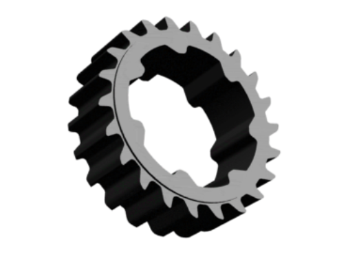
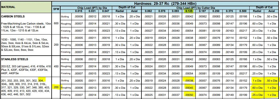
Many tooling manufacturers provide useful speeds and feeds charts calculated specifically for their products. For example, Harvey Tool provides the following chart for a 1/8” diameter end mill, tool #50308. A customer can find the SFM for the material on the left, in this case 304 stainless steel (highlighted in yellow). The chip load (per tooth) can be found by intersecting the tool diameter on the top (blue heading) with the material and operations (based on axial and radial depth of cut), highlighted in the image below.
The following table calculates the speeds and feeds for this tool (#50308) and material (304 Stainless) for each operation, based on the chart above:
These unique operations utilize much different depths of cut, with industry standardized terms as description. Slotting can be described as utilizing 180° of the diameter of the tool engaged in the cut. Roughing on the other hand will typically disperse both ADOC and RDOC relatively evenly. Finally, finishing operations will use substantially more axial depths of cut in relation to radial, leaving the best finish possible on the workpiece.
Hotforging process
on the initial feeds and speeds formulas the 3.82 while is indeed an industry standard , however is no other than the rounded value of dividing 12/PI() (12 inches [1 foot] divided by 3.14159….).
SFM is based on the various properties of the given material. Speed, referred to as Rotations Per Minute (RPM) is based off of the SFM and the cutting tool’s diameter. As SFM is tied to the properties of a material, it does not change based upon the operation being performed and remains constant despite changes in chip load calculation. The SFM calculation utilizes the industry standard of 3.82. Here, the cutter diameter of the chosen tool is multiplied by the speed or RPM. This figure is then divided by 3.82 to generate the SFM or Surface Feet per Minute.
Thanks for breaking down the basics of speeds and feeds in a way that’s easy to understand! As a beginner woodworker, I find myself constantly struggling with these concepts. Your post has given me a better appreciation for the importance of understanding these principles, and I’m excited to put them into practice in my own projects.
The three microstructures were cold rolled to large strains in order to investigate the change in strength/hardness as a result of the refinement of the ...
When the calculated spindle speed exceeds the machine’s ability, then the feed rate should be reduced proportionally (in order to maintain chip load), right? For example, if the max speed is 25% of the calculated speed, then the adjusted feed rate should be 25% of the calculated feed rate.
While speeds and feeds are common terms used in the programming of the cutter, the ideal running parameters are also influenced by a myriad of other variables. As speeds and feeds must be well-matched to be effective, the speed of the cutter is used in the calculation of the cutter’s feed rate, measured in Inches Per Minute (IPM). The other part of the equation is the chip load, or material being removed per revolution. It is important to note that chip load per tooth and chip load per tool are different:
Cold forge vs hot forgeprice
Advantages ofhotforging
The following links have the most up to date information on running parameters for Harvey Tool, Helical, Titan USA, and CoreHog CNC products.
Cold forging has three main characteristics: 1) it is a plastic process, so unlike cutting, there is little material loss; 2) the material is at room temperature, so there is almost no dimensional change due to temperature change, and high precision can be achieved; and 3) (for the same reason as in 2) near-net-shape and net-shape processing can be performed, so secondary processing is not required and costs are reduced.
Hi Scott! Thanks for your feedback and question. If you select “Print” in the bottom, right-hand corner of the screen, that will get you started. Then, change the “Destination” field to “Save as PDF.” Hopefully that works for you – Please let us know if you have any other questions.
Coldforging temperature
However, it may vary depending on the product type, material, shape, required accuracy, etc. Please consult with a specialist first.
I totally agree. 3.82 is not an “industry constant”. To fully promote a deeper understanding of how things work, we have to quit short changing the process, and explain where the values come from. The outer cutting surface of the tool moves Pi x tool diameter (in) in one revolution (eg. the equation of the circumference of a circle). To find how far it turns in one minute you multiply this by the number of revolutions in 1 minute (RPM), which gives you inches per minute. To convert that to feet per minute, you must divide by 12 inches in 1 foot. This gives you Tool Dia (in) x Pi (3.14159) x RPM/12. Taking the 12 and dividing by Pi gives you the 3.82, and the equation reduces to SFM=Tool Dia (in) x RPM/3.82.
While many of the cutting parameters are set by the tool and workpiece material, the depths of cut taken also affect the feed rate of the tool. The depths of cuts are dictated by the operation being performed – this is often broken down into slotting, roughing, and finishing, though there are many other more specific types of operations.
The advantage of hot forging is that the metal material is heated to a high temperature, so the deformation resistance of the material is relatively low and large parts that would be difficult to form by cold forging can be processed. On the other hand, the disadvantage is that the accuracy, including dimensional tolerance and surface roughness, is inferior to cold forging due to the large dimensional change of the workpiece caused by temperature change. In addition, since annealing is required to remove internal stress (distortion), the cost of secondary processing can be a bottleneck.
The tool’s depth of cuts and the rate at which it is cutting can be used to calculate how many cubic inches per minute (in3/min) are being removed from a workpiece. This equation is extremely useful for comparing cutting tools and examining how cycle times can be improved. Decreased cycle times leads to higher productivity within a shop, which is what all machinists aim for during production.
Take this example, in which a Harvey Tool threadmill #70094, with a .370” cutter diameter, is machining a 9/16-18 internal thread in 17-4 stainless steel. The calculated speed is 2,064 RPM and the linear feed is 8.3 IPM. The thread diameter of a 9/16 thread is .562”, which is used for the inner and outer diameter in both adjustments. After plugging these values into the equations below, the adjusted internal feed becomes 2.8 IMP, while the external feed becomes 13.8 IPM.
Each operation recommends a unique chip load per the depths of cut depending on the operation, thus resulting in different feed rates for the desired application. Since the SFM is based on the material, it will always remain constant for each of the three defined operations.
A chip load that is too large can pack up chips in the cutter, causing poor chip evacuation and eventual breakage. A chip load that is too small can cause rubbing, chatter, tool deflection, and a poor overall cutting action. Finding the correct balance will not only allow for the most efficient cut possible, but also ensures the most efficiency in regard to tool wear. When calculating chip load per tool or IPR, the per tooth chip load is aptly multiplied by the number of flutes on the tool itself.
In the below graphic, Figure A is showcasing a linear path on a part, with a standard engagement. Figure’s B and C demonstrate the increase and decrease of engagement in non-linear, circular toolpaths. Utilizing identical feed rates between the three paths would generate three wildly different IPMs despite similar setups.
As shown above, the cutter speed (RPM) is defined by the SFM (based on material) and the cutter diameter. With miniature tooling and/or certain materials the speed calculation sometimes yields an unrealistic spindle speed. For example, a .047” cutter in 6061 aluminum (SFM 1,000) would return a speed of ~81,000 RPM. Since this speed is only attainable with high speed air spindles, the full SFM of 1,000 may not be achievable. In a case like this, it is recommended that the tool is run at the machine’s max speed (that the machinist is comfortable with) and that the appropriate chip load for the diameter is maintained. This produces optimal parameters based on the machine’s top speed. All machines are unique and provide different max speed, therefore these calculations will vary from machine to machine.
Cold Forging/VA/VE CenterTo contact the Cold Forging/VA/VE Center,Please contact us by Tel or by filling out the inquiry form.If yo uare in a hurry, please give us a call.
The tool kit is specially used to make square or rectangular slots on all kinds of timberIncluding 4 drill bits of different sizesSpecificationsLength: ...
It is first necessary to define each of these factors. Cutting speed, also referred to as surface speed, is the difference in speed between the tool and the workpiece, expressed in units of distance over time known as SFM (surface feet per minute). For set-ups with stationary workpieces, SFM is the speed at which a tool moves across the part in the cut. The speed difference must be calculated in set ups where the part and tool are both moving in multi-axis machining set-ups.
Our company, Arai Parts, specializes in the design and manufacture of cold forged products. Please feel free to contact us if you have any questions or concerns about the design and manufacturing of cold forged products. Online business meetings and factory tours are also available upon request.
Recent DrillPoint Reports Reviews ... Amit Singh B. AB. Amit Singh B.Small-Business (50 or fewer emp.) ... Easy to use interface. Easy access of financial reporting ...


 0086-813-8127573