
Stainless Steel Machining - steel machining
It’s a good idea to be verbose with what dimension you are referring to in the From and To columns so that your thinking can be more clearly communicated to a reviewer and to give yourself a reminder during design.
The Footprint Hand Drill No. 150 was officially listed and advertised as the 'Footprint Combination Hand Or Breast Drill No. 150'. The drill is equipped with a breast drill handle to help with steadying and then a hand drill handle set unusually at an angle.
Each time a tolerance analysis is conducted it can generally be split into three steps: Prepare, Stack, and Adjust (or PSA). The whole tolerance analysis should be conducted twice. First, you want to take an early look in the Architecture Phase to determine if the general design planned is feasible from a tolerance perspective. Secondly, you will want to revisit your design in the Detail Design Phase before release to make sure you can confidently purchase parts without worrying about tolerance stack issues.
The Stanley router number 71 is a two-handled hand tool used for cutting, cleaning and smoothing grooves. The Stanley 71 is referred to as an open throat router due to the raised hollow arch at the front of the router.
Findbuy tool Planer
This review contains photos and info about the Record 053 spokeshaves also referred to as the adjustable mouth Record spokeshaves. The adjustable mouth / throat allows the user to adjust the thickness of shaving between coarse workings through to fine work.
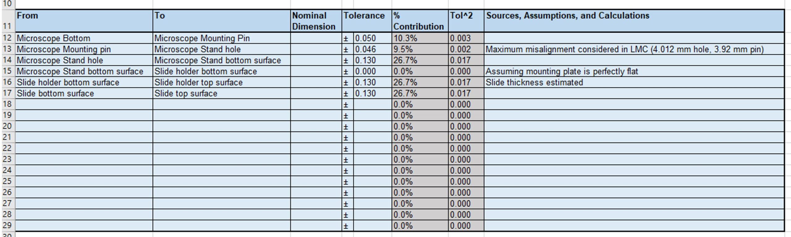
The rest of the tolerances are machining tolerances between features on the microscope holder, slide holder, and slide. We can enter that information into the spreadsheet as shown. Notice how each dimension is fully described in order from the microscope to the slide.
The Record block plane number 015 is fully adjustable block plane from the Record plane range. The 015 adjustable features includes an adjustable mouth and adjustable blade controls; both depth and lateral movements.
Please note that the process described in this post is a smaller outline of a more detailed process described on my whitepaper. For a more rigorous study of making a tolerance analysis and the tolerance stack, check out my whitepaper.
This Veritas Low Angle Jack Plane review is of the plane made by Veritas Tools of Canada, the review contains lots of info, photos and videos. The Veritas Low Angle Jack Plane is a fully adjustable, low angle jack plane designed for shooting mitres, working end grain and initial smoothing.
This Lynx One Man Log Saw review covers the Log Saw made by Thomas Flinn & Co (Sheffield). The Lynx One Man Log Saw is a traditional saw used for cutting logs quickly by hand. The saw can also be used as a Two Man Saw.
Find toolscatalog
Neil Foxman is a Senior Systems Engineer at Simplexity’s San Diego office. In 2014, he graduated with a Bachelor of Science in Mechanical Engineering from Tufts University and has since taken Electrical Engineering master’s degree courses at University of California, San Diego. Since joining Simplexity in 2015, Neil has worked on a variety of mechanical, electrical, and software designs.
Simplexity typically engages with production component suppliers and contract manufacturing groups early in this phase to provide additional manufacturing input on the design. If the product has stringent testing or certification requirements, pre-screens are performed in this phase prior to formal regulatory agency testing.
Simplexity has a dedicated New Product Introduction (NPI) team that can guide the transition from design into production. The NPI team presents multiple options for manufacturing to the client, allowing clients to choose the solution that best suits their needs. This can involve Simplexity performing initial builds in-house prior to full handoff to a contract manufacturer or building the product via established relationships with contract manufacturing partners either domestically or overseas early in the process.
Finally, make sure the tolerances mentioned on the tolerance stack match the tolerances used on the mechanical drawings. Once your drawings and tolerance analysis spreadsheet are aligned, your tolerance analysis is completed, and you are ready for release!

This blog will continue examining the example mentioned earlier: A microscope fixture. A rough sketch of the parts envisioned for this design are shown below.
Isfindbuy tool legit
We first enter the tolerance from the microscope bottom to the microscope mounting pin. Enter the description of the relevant features in the From and To columns and the numerical tolerance on the top line. Ignore the nominal dimension column for this study, and don’t change the formulas in the gray columns because these will update automatically. The second section in your tolerance stack should now look like this:
Careers at Simplexity Employment Verification Join our Mailing List! Privacy Policy Simplexity Product Development Copyright © 2024 | All Rights Reserved
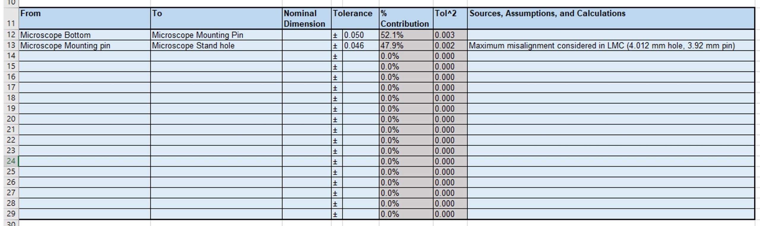
To capture this possible misalignment in our tolerance stack, we need to add another line showing this position tolerance possibly including some notes on how this tolerance was achieved.
Find toolscatalogue
The Stanley block plane number 140 is a skew block plane (with an angled mouth) and usually a Rosewood wooden front knob. The right hand side of the plane (as looking from the rear) is detachable. The side is held in place by two screws.
Let’s plan to fit the mounting pin on the microscope into a clearance hole on the microscope stand. Looking again at the microscope datasheet, we see that the mounting pin has a diameter of 3.95 ± 0.03 mm. A common ISO 286 tolerance zone for a hole is H7 which has an asymmetric 0.012 mm tolerance zone (4.000 +0.012, -0.000 mm). For other hole/shaft fits, you can use the tool on Engineer’s Edge. This tolerance zone is asymmetric, but we will revisit this fit in the stack phase to see how it can be used.
Even if the production methods allow you to design tight tolerances on a single part, you need to consider the tolerances of all the parts around it to make sure that the overall system functions correctly.
I would recommend looking for tolerances on rapid prototyping manufacturer websites. Most prototyping manufacturers automate their process, so they are more likely to post tolerance information online. For instance, we commonly use Protolabs for machining prototype parts, and they have good design guides with tolerances for CNC milled parts, CNC turned parts, and sheet metal parts.
Now that we have an idea of the relevant part tolerances, it’s time to create our Tolerance Stack using the template provided. Let’s enter each tolerance found earlier into the spreadsheet. It helps if there is a logical order to the tolerances entered in the spreadsheet, so we will look at each dimension along the way from the bottom of the microscope to the top of the slide.
Finally, the slide thickness will have its own tolerance. If we are early in the design process, we can do a Google search for glass slide manufacturers and take a rough guess at the slide thickness tolerance assuming we will revisit it later. In this case let’s assume we contacted our slide manufacturer, and the manufacturer quotes their thickness tolerance zone to be within 0.13 mm.
"Just stumbled across your website and an absolute treasure trove of information. I was recently given an old Stanley 110 block plane and wanted to know more about it. Your website told me everything I needed to know. But there is so much more to read. I forsee me spending a lot of time just reading page after page. I can appreciate how much time this will have taken to put together. I just wanted to let you know that your hard work is appreciated."
First, we will focus on technique 4: introducing compliance into the system. This concept introduces more complexity to your design, but it is likely to significantly reduce the total tolerance stack of your system. Instead of fixing each part at a single position and making the machining tolerances tight for all the parts, consider allowing most of the parts to have loose tolerances or move in space. Then introduce an engagement step or clamping step where the critical parts are aligned with a single part.
Find toolsreviews
Find toolswebsite
This Ashley Iles Wood Carving Tool review covers the tools made by Ashley Iles (Edge Tools) Ltd, England. Ashley Iles wood carving tools are made to traditional standards using traditional techniques and craftmanship.
Looking for information about a hand tool? Find-My-Tool is an extensive tool directory of new tool reviews and old hand tool reviews (we are currently working on both old tool reviews and new tool reviews). The perfect place to find info about specific antique tools, old tools and new hand tools. Each tool review is depicted with professional images and a wealth of interesting information...
Tool finder app
Transforming your mechanical CAD designs into real and tangible parts is one of the most rewarding feelings as an engineer. However, a lot of things can go wrong during this transition. One of the most common and most overlooked problems are tolerances. Have you ever tried mounting your TV on your wall, but the holes don’t line up perfectly? Or do you have to jiggle your keys every time you open the front door? These issues occur because of poorly controlled tolerances.
For now, the focus of this exercise is the top line of this section: Arithmetic Stack (Worst Case). The value in the tolerance column represents the sum of all the tolerances in the stack. It looks like we will currently not be able to meet the requirements because our total possible misalignment is ± 0.486 mm but our requirements state that we need to be within ± 0.25 mm. We now need to make some fixes to the architecture which we will do in the next step, Adjust.
The Chesterman Constantia tape measure has a woven linen tape, a brass winder and a solid leather, hand-stitched, lined case with a special waterproof lining. The tape typically measured with the measurement commencing from the outside of the ring at the end of the tape.
The Disston D8 hand saw was the most widely produced saw out of the range of Disston saws. There were many variations of the D8. The handles on old D8 saws were usually made from Apple wood. Later D8 saws were made from selected hardwoods, usually Beech.
So far, we have been using the Arithmetic Stack (Worst Case) row to determine if the design is feasible. In the list of possible design adjustment techniques above, we may also consider technique 6 for our example which analyzes the stack using the Statistical Stack (RSS) or Adjusted Stack (RSS * 1.5). These calculations use the Statistical perspective of the tolerance stack: it is unlikely that all the parts will be at their absolute worst case condition at the same time, so statistical methods (RSS) can be used to better quantify a more realistic and smaller tolerance zone. The RSS stack multiplied by a factor of 1.5 is sometimes preferred as a more conservative estimate.
Enjoy viewing the encyclopedia of tools. If you are inspired by our content or use info such as dates, sizes, details from FindMyTool.co.uk please kindly give credit where credit is due via giving a nod in a video or a link to this website. Please see our terms if using more than a few dates or details.
Although every project is different, if you remember to Plan, Stack, and Adjust during each of your tolerance analyses, you can quantify the total tolerance of your system, and more confidently release your mechanical designs for production.
Because tolerance analyses are often done before detailed design is complete, I highly recommend making a rough block diagram of your system. Basic diagrams clarify important interfaces and dimensions before the design is detailed, and they serve as an important tool for communicating your findings at design reviews.
Tolerance analyses don’t just apply to mechanical parts; in the engineering world, most measurements are approximate and knowing the tolerances of the components you buy can help you better gauge the performance of the overall system. For example, most electronic components have tolerances associated with their values, or operate within a range of acceptable supply voltages or currents.
Next, some care needs to be taken when considering the fitment between the microscope mounting pin and the hole in the microscope holder. Because this is a clearance hole, there can be some misalignment, and we need to consider the worst-case condition for our tolerance stack. In this case, we get a maximum misalignment of the microscope to the microscope holder in the Least Material Condition where the hole is at 4.012 mm and the pin is at 3.92 mm. This means that there is a possible misalignment of 0.046 mm as shown below.
Let’s look at an example design: a microscope fixture. The bottom surface of our microscope needs to be held at a specific height above a slide (6 ± 0.25 mm), so we plan to design a microscope stand, a slide holder, and a mounting plate for the parts to be mounted on. We plan to machine all the parts using a CNC milling machine which has an accuracy of ± 0.2 mm. The machining tolerance zone is smaller than the required tolerance zone, so no problem, right?
This Veritas Skew Block Plane review covers the Veritas Skew Block Plane made by Veritas Tools of Canada. The Veritas Skew Block Plane is a fully adjustable, multi-function plane which packs a great punch.
The detailed design phase usually has multiple, iterative sub-phases as the design progresses and representative prototypes are built. Phases 2B and 2C are typically the largest efforts in the product development process, where the specific implementation for all disciplines occurs (mechanical, industrial design, electrical, firmware, systems, software, manufacturing, and quality).
Phase 2C iterates on the learnings of Phase 2B and involves a refined prototype build of a fully integrated system. Some projects also benefit from additional iterations of the product based on prior learnings through additional phases (2D, 2E, etc), which are not represented in this graphic. All requirements are intended to be tested, and at the end of Phase 2 there will be confidence that the units will pass verification in Phase 3. The Bill of Materials is further refined, and the team updates estimates for the per unit cost of the product by receiving pricing from vendors and suppliers.
Categories: Engineering & Analysis, Product Development & Design, Mechanical Engineering, Prototyping & Manufacturing, Simplification
Sometimes the tolerances are just too tight to design around, and you need to start looking at more expensive operations. Some additional options are listed below.
Now that you have a better sense of the parts used in the stack, you can start finding each part’s manufacturing tolerances. In the Architecture Phase the goal is to get a rough-order-of-magnitude or “ROM” estimation of each part’s tolerances to catch if your design is way off and needs larger architectural or manufacturing changes.
The Stanley jointer plane number 8 is the longest of the standard Stanley bench planes at approximately 23 7/8 inch (606mm) in length, 80mm wide with a 66mm (2 5/8 inch) wide plane blade. This plane is often referred to as a Stanley jointer plane.
For tight tolerance applications, you will commonly find yourself adjusting the tolerance stack or the mechanical architecture to meet the requirements. If the designed tolerances are too loose, you can try some of the following techniques.
Next, we can assume that the microscope stand and slide holder are made using a CNC milling machine, so we would like to find some tolerances for these parts. Looking at our manufacturer website, they claim that their usual machining tolerance is 0.005” (0.13 mm).
The detailed design phase starts with defining options for the product architecture, with the goal of having the greatest chance of successfully meeting product requirements while best mitigating risk. Engineering activities in this phase include presenting options for hardware components, outlining the system block, sequence, and state diagrams, creating rough CAD, and breadboarding of high-risk subsystems. Results are presented with a description of the pros, cons, and key tradeoffs for each scenario.
Tool Finder
Well, actually no. Each of the machined parts may be 0.2 mm away from what we want. So, if the microscope stand is 0.2 mm taller after machining, and if the slide holder comes out 0.2 mm thinner, then the slide would actually be 0.4 mm away from the nominal 6.0 mm, causing the image to be out of focus.
In the Detail Design Phase, you will want some more confidence in the tolerances you are researching which may entail contacting specific suppliers and comparing different supplier tolerances. For injection molded parts and cast metal parts, a vendor may provide you with a Design for Manufacturability (DFM) document that highlights issues with your design. Even if the manufacturer had previously quoted certain tolerances, the tolerances may be adjusted (for better or worse) after a rigorous DFM that looks at thin features or possible warping during manufacturing.
Although the microscope fixture uses generally simple part geometries, it’s worth noting that you should try to visualize how each part will be made, as some production methods can have vastly different tolerances depending on the part orientation. For instance, sheet metal tolerances between two edges on the same plane can have much tighter tolerances than the dimension between an edge and a bend as shown below. 3D printed parts may also be sensitive to the build orientation. In general, machined parts have tighter tolerances when the part is only held in one orientation, but tolerances increase between features when the part is flipped or moved within the machine. For all these manufacturing methods, smaller dimensions may also have tighter tolerances than larger dimensions.
The design team works closely with the manufacturing team to enable a smooth transfer, often with Simplexity engineers traveling to the contract manufacturer sites to ensure product quality. The design is transferred to the client based upon specific needs, most often after all tests are complete and the design is verified.
In our microscope holder example, this could be a custom designed Microscope Head that is spring loaded against the top surface of the slide. In this case we don’t care as much about the tolerances of the other parts, and only need to control the dimension between the Microscope mount features and the slide surface. Our system and tolerance stack would then look like:
If you need to make architecture or manufacturing changes, repeat the process: Prepare and research what the updates entail, add or remove parts in the Stack, and Adjust the design until the tolerances are reasonable and you can proceed with more detailed design.
We are now within our target tolerance zone! This architecture should work for our design, but it’s worth noting that the complexity has increased: you now have to design the spring mechanism and investigate if the additional forces on the slide cause it to break or warp.
In a case like this, you would need to do a tolerance analysis of the tolerance stack-up to make sure the design will work. A tolerance analysis looks at all the relevant tolerances in a system and adds them so that we can improve the design to meet a certain design requirement. A tolerance stack-up analysis is usually done on a spreadsheet. Feel free to use this template to get started. We will be using this template later in this article to walk through the analysis.
We will plan to mount the microscope on the microscope stand using some alignment features. Assume our microscope has a datasheet that claims the tolerance between the bottom of the microscope and a mounting pin is 0.05 mm.


 0086-813-8127573